Once this is verified, start the crane, and find the magnetic limits of the crane. When the main screen
is shown, the driver can be adjusted.
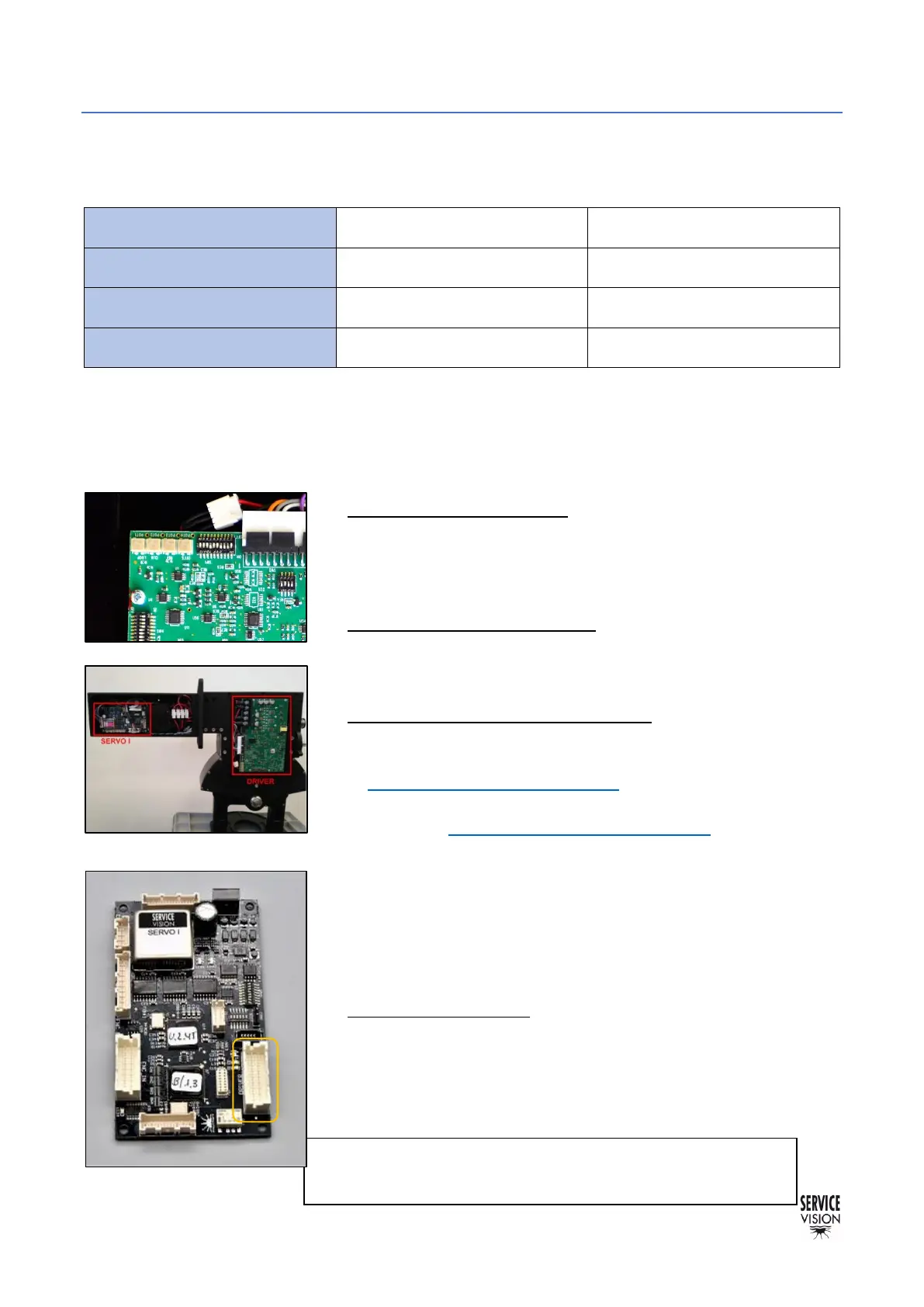
There are 4 potentiometers in the connectors side. These potentiometers adjust different parameters
of the behavior of the motor and there is no mechanical limit on the numbers of turns they can do.
• Potentiometer 1 Loop Gain: Turn the potentiometer number 1
CLOCKWISE until hearing a “coupling” noise from the motor.
From this point, turn counterclockwise now until the “buzz” noise
stops. And from this exact point, keep turning counterclockwise for
1,5 turns more and stop. Try to be as accurate as possible.
• Potentiometer 2 Current Limit: Always needs to be giving the
maximum current. Turn the potentiometer number 2 CLOCKWISE
until hearing a “click” noise or during 15 full turns CLOCKWISE to
reach its maximum.
• Potentiometer 3 Ref in Gain / SPEED: To adjust the speed it is
mandatory to DISENGAGE the motor of the crane. Switch off the
Electronic Box and remove the belt for the leveling head as seen
in chapter 6.4.1 Belts on the crane. Then change the SERVO I
Switch SAd1 direction to MOTOR FREEWHEEL (1,2,3,4 ON)
(check the chapter 9.3 Other documentation). Switch on the
Electronic Box again and turn the potentiometer clockwise 15
times then turn counterclockwise slowly until the noise of the
motor changes. With the help of a multimeter, keep adjusting until
the voltage value in the Motor Power Terminals (MA, MB) is
between 27V and 28V (any value into this range will be considered
as correct). Switch off the Electronic Box and set the SERVO DIP
switch 1 as it was (2,3,5 ON).
• Potentiometer 4 Offset: Remove the DRIVER connector in the
Servo I board, checking if there is any movement in the motor. If
so, turn the potentiometer clockwise or counterclockwise until the
movement disappears. Connect the DRIVER connector of the
Servo I board again and engage the motor to the mechanics again
with the belt.
 Loading...