3.7
3.2.3. External autocalibration connection
The external autocalibrate initiate input is located at pins 11 and 12 of connector PL5. The
autocalibration facility is started by shorting these two pins together or by providing a digital low
signal to pin 12.
For analysers configured with the external autocalibration option card, an additional output
connector, PL8, is fitted into the sample gland plate at the rear of the analyser. This connector
supplies two pairs of relay contacts which may be used to control external valves.
The following truth table applies to any pair of relay contacts utilised for autocalibration. These
relay contacts are rated at 1.0A, 264V AC and 1.0A, 30V DC (non-inductive). Screened cable
should be used to connect to solenoid valves of length not exceeding 3m with the screen
terminated at the instrument end. It will be necessary to fit a suppression device across the
coils of the solenoid valves. For DC supplies a diode is recommended. For AC supplies a
0.047uF capacitor in series with a 100
resistor would generally be found satisfactory.
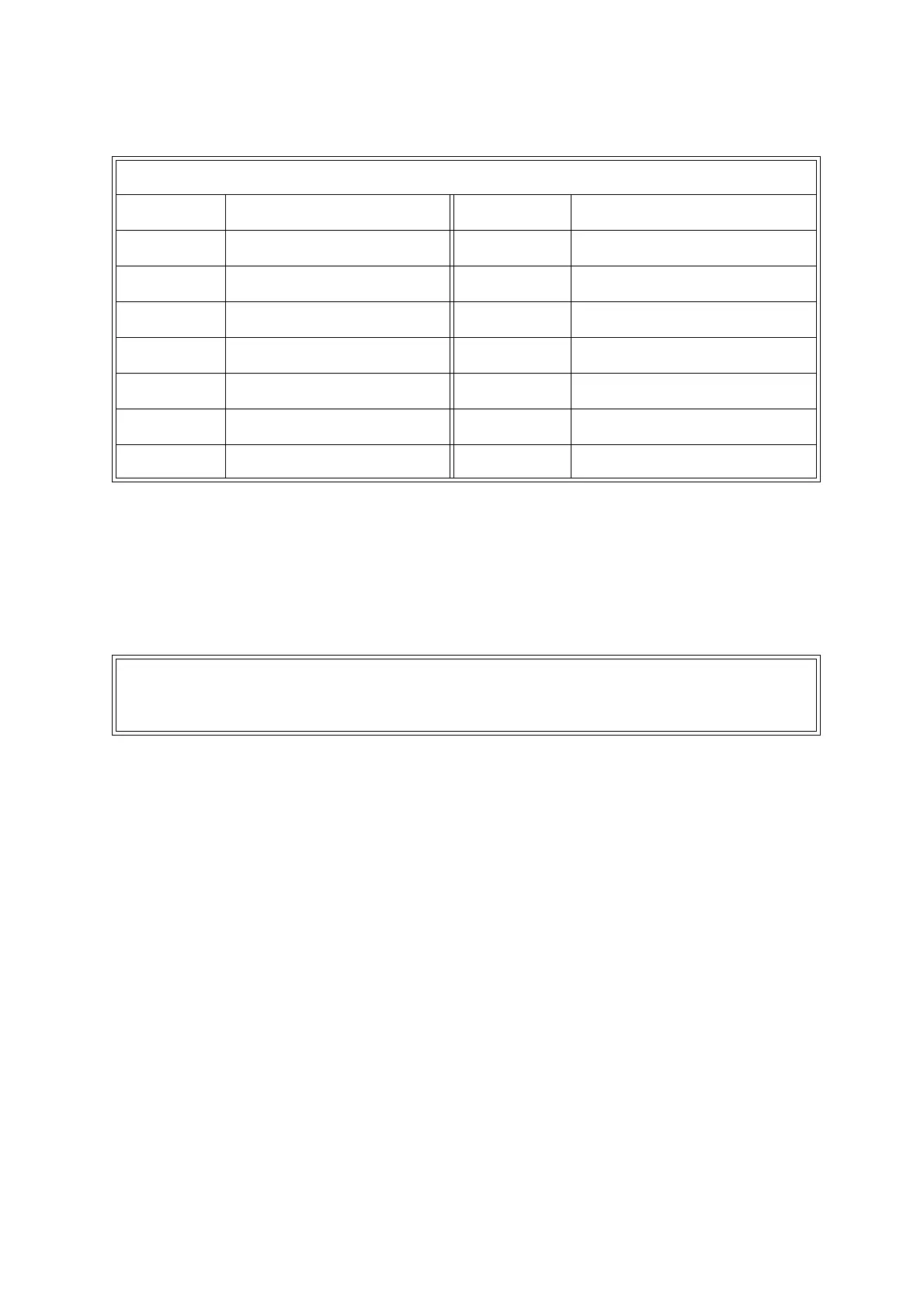
Table 3.3: Signal terminal location PL5
Terminal Function Terminal Function
1 Analogue input 1 +ve 8 0V
2 Analogue input 1 -ve 9 Analogue input 1 valid
3 Analogue input 2 +ve 10 0V
4 Analogue input 2 -ve 11 0V
5 Screen 12 Auto calibration initiate
6Screen 130V
7 Analogue input 2 valid 14 Range change
NOTE
The external autocalibration initiate signal should be applied for at least 2 seconds,
(but less than 30s) to ensure that the input has been recognised.

 Loading...


