3.9
3.4 Continuous mode
In continuous mode a data frame is transmitted by the serial output port at a user defined
interval. The format of the data frame is given in Table 3.6 and 3.7. However, it is a list of
process variables (or 'fields') preceded by a start character, separated by semi colons and
terminated by carriage return and line feed, i.e.:
A;B;C;D;E;F;G;H;I;J;K;L;M;............;N;<CR><LF>
The frame frequency and generic communications parameters are configured in the analyser
software (refer to Quickstart manual), note the 'frame frequency' sets up the frequency of
transmission of the data frame down the serial communications port. For example if the value
is set to 15 seconds then the output data frame will be transmitted once every 15 seconds. The
frequency is set in steps of one seconds from 1 to 9999 seconds. If the value is set to zero then
the transmission of data down the serial port stops and will not restart until a non zero value is
entered.
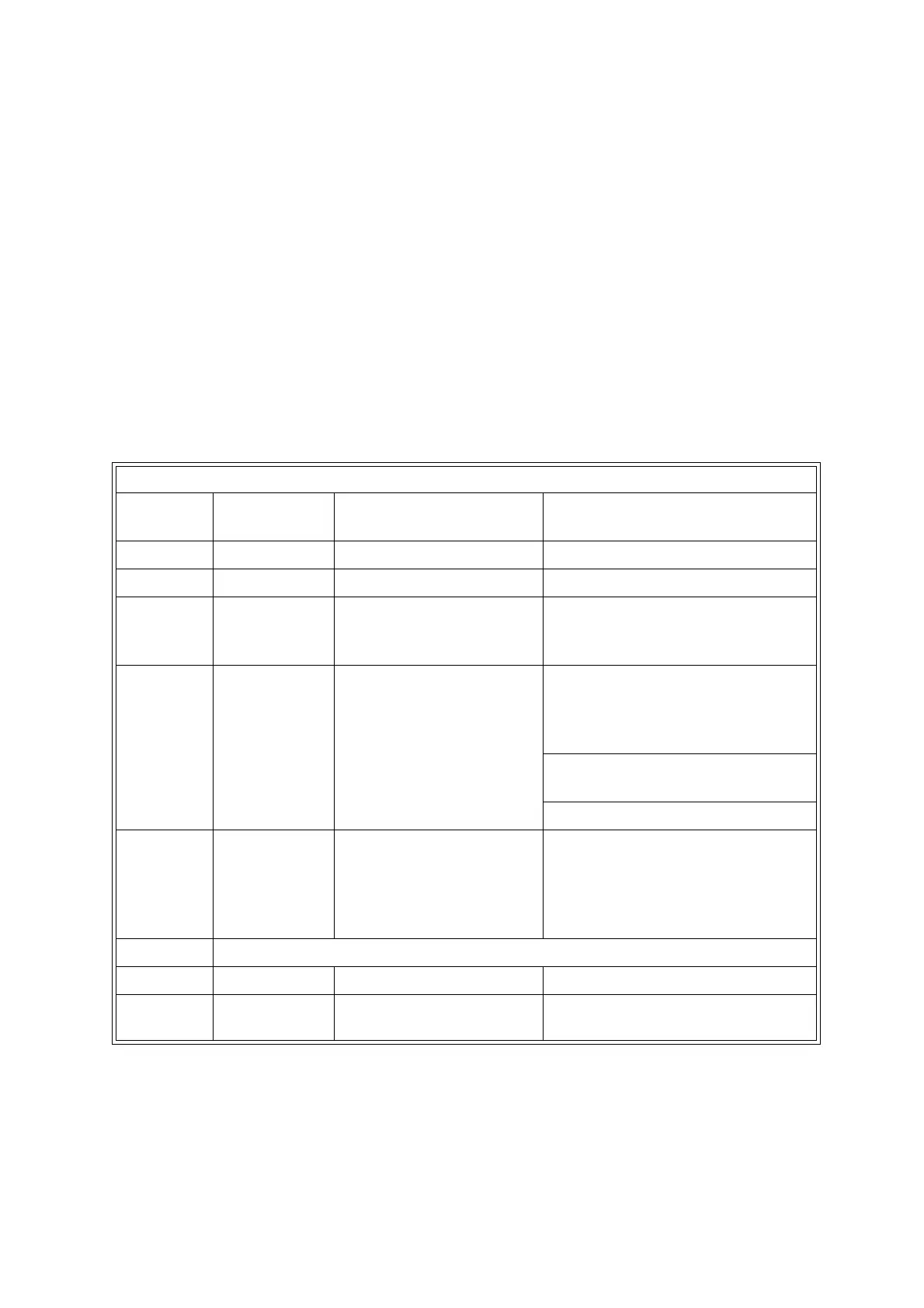
Table 3.6: Serial output data frame, start and end sequences
Field Number of
characters
Function Entry/format
A 8 date DD-MM-YY
B8time HH:MM:SS
C 2 analyser failure and
maintenance fault status
first character F for failure, second
character M for maintenance
(spaces = OK)
D 8 Autocalibration 'flags',
two characters for each
of the four calibration
groups
first character: group 1, S for
sample, C for calibration gas
second character: group 1, 1 for
cal gas 1, 2 for cal gas 2
etc, for groups 2, 3 then 4
E 2 number of process
measurements or
'variables'
03 to 07, the following fields will be
repeated for each transducer and
any derived measurements. The
last two variables will always be
the two external inputs (E1, E2)
F-M measurement sequences, refer to Table 3.7
N 4 check sum e.g.: 096A
- - end code, <CR> and
<LF>
ASCII code 13 and 10

 Loading...


