6
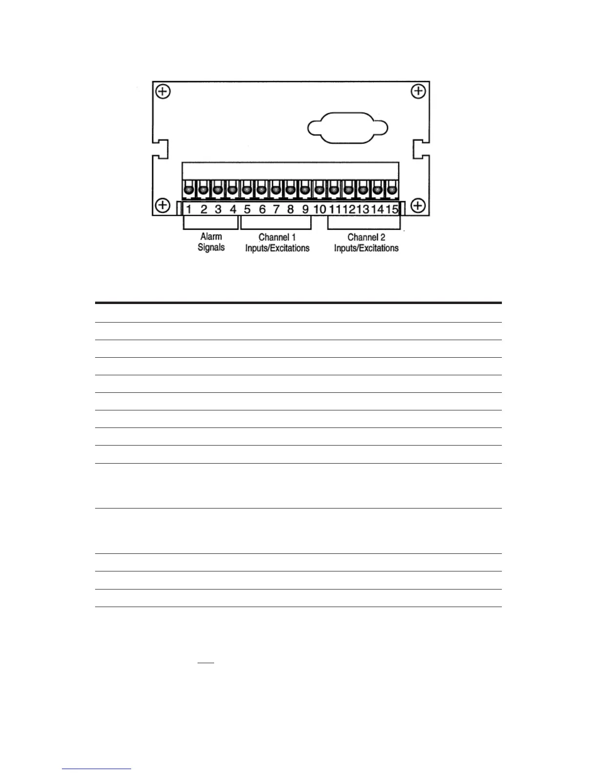
Figure B
Terminal block connector
Pin Description
Setra transducer* Setra transmitter*
w/ red cable w/ gray cable w/ gray cable
1 Ground
2 Hi ALArm
3 Lo ALArm
4 Ch. 1/ Ch. 2
5 +24 volts excitation White Red Red
6 Ch. 1 +In Yellow Green
7 Ch. 1 -In Brown White
8 Ch. 1 current input Black
9 Ground Black/Shield Black/Shield Shield
10
+12 volts excitation (optional)
Caution: Do not common to
pin 5 or pin 11 (+24V exc.)
White White
11
+24 volts excitation
Caution: Do not common to
pin10 (+12V exc.)
White Red Red
12 Ch. 2 + In Yellow Green
13 Ch. 2 - In Brown White
14 Ch. 2 current input Black
15 Ground Black/Shield Black/Shield Shield
*
Important: If you are not using a Setra transducer or transmitter, see manufacturer’s
transducer/transmitter operating instructions for terminal circuit conguration and
then connect the wires to the corresponding pins listed in the above chart.