5
2.3 Transmitters (4 wire or 4 terminal devices)
Connect the + excitation to pin 5 (CH2: pin 11) to supply 24 volts to the transducer.
If your transducer requires 12 volt excitation, connect the + excitation to pin 10
(CH2: pin 10).
Connect the - excitation to ground, pin 9 (CH2: pin15).
Connect the + output to +IN, pin 6
*
(CH2: pin 12).
Connect the - output to -IN, pin 7
*
(CH2: 13).
Connect the shield to ground, pin 9 (CH2: pin 15)
*
Note: THE OUTPUT OF THE SETRA TRANSDUCER INSTALLED IN THE DATUM
2000™ MANOMETER IS AVAILABLE ON PIN 6 AND 7. DO NOT APPLY AN
ELECTRICAL SIGNAL TO CH1: PIN 6 OR CH1: PIN7. A SECOND TRANSDUCER
MAY BE CONNECTED ONLY TO CH2: PIN 12 OR CH2: PIN 13.
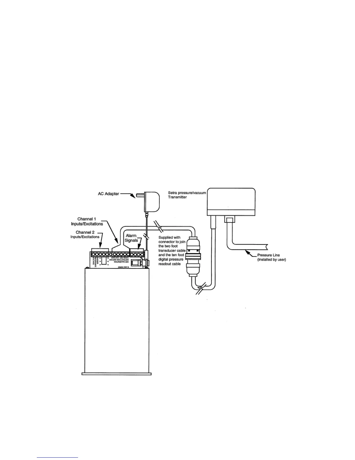
Figure A