Appendix A • Super II 105
The RS232 Interface Hardware
Although Setra scales can communicate with almost any RS232 device, the built-in interface does not
include the complete protocol. Only the transmit and receive lines of the standard interface are used on
the OUT and IN ports respectively, and the transmit, receive, RTS and CTS lines on the BI port.
The default data format is: 1 start bit
8 data bits including parity
1 stop bit
10 bits per frame (framing errors ignored)
NOTE: The scale will transmit using the parity selected; however it does not check the parity it receives.
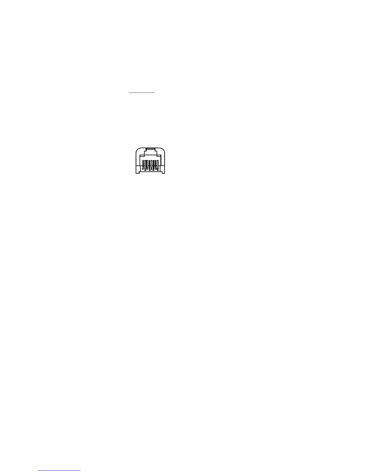
All serial ports use an eight pin modular connector. The pinout is as follows:
BI OUT IN
1. ground 1. ground 1. ground
2. transmit out 2. transmit out 2. no connection
3. receive in 3. no connection 3. receive in
4. RTS (Request To Send) 4. Alarm 1 4. Digital Input 1
5. CTS (Clear To Send) 5. Alarm 2 5. Digital Input 2
6. no connection 6. no connection 6. +5V
7. ground 7. ground 7. ground
8. ground 8. Alarm 3 8. Digital Input 3
NOTE: The “handshake” signals “Clear To Send” (CTS) and “Request to Send” are implemented on the BI poer
only. This requires that the peripheral attached to the IN and OUT ports have a minimal buffer (15 charac-
ters).
In addition, some computers requiring hardware handshaking will need a connection between two pins
on the computer’s connector named DTR and DSR (Data Terminal Reading and Data Set Ready).
The maximum recommended cable length is 15 meters. The cable may be longer if it has less than 2,500
pF capacitance. The load impedance of the device connected should be between 3,000 and 7,000 ohms
with not more than 2,500 pF shunt capacitance. For more information, consult EIA Standard RS232: “Inter-
face Between Data Terminal Equipment Employing Serial Data Interchange.”
Modular Jack
Connector
(in back of scale)
8 1
Modular Jack
Connector
(in back of controller)
 Loading...