Appendix C • Super II 114
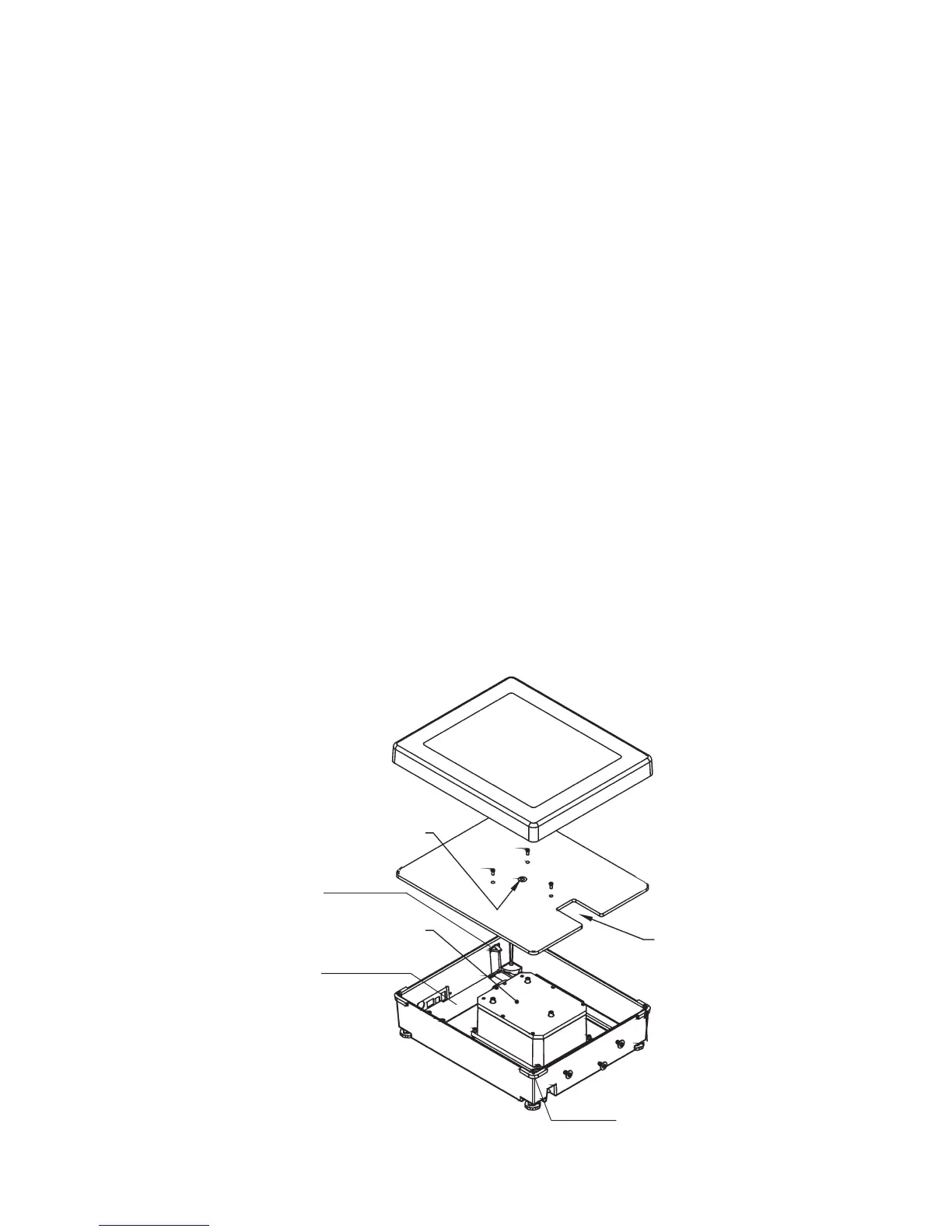
PAN
PAN SUPPORT
BASE
BUBBLE LEVEL
LOAD CELL
MODULE
TRANSPORTATION
HOLDER FOR THE
AC ADAPTER
PAN SUPPORT
STOPS
Figure 1
A
A
A
BATTERY DOOR
REAR POWER
CIRCUIT BOARD
Appendix C
Battery Option
Installation
Disassembly of the scale is required when installing the battery option kit.
1. Remove the pan and the pan support by removing the 3 screws marked “A” in Figure 1.
2. Remove the (2) Phillips head screws (marked “B” in Figure 2) and the rear panel.
3. Next remove the (4) Phillips head screws holding the rear power circuit board to the base casting.
4. Disconnect the rainbow cable and coiled cord. Remove the rear power circuit board.
5. Install the battery option circuit board and reconnect the rainbow cable and coiled cord. Make sure to loop the battery
connector out through the battery door opening.
6. Replace the (4) Phillips head screws to hold down the battery option circuit board.
7. Exchange the rear panel with the panel cut to accomodate the ON/OFF switch. Mount the new rear panel onto the scale
with the (2) Phillips head screws (marked “B” in Figure 2).
8. Remove the battery door, attach the battery connector to the battery, then insert the battery (cable end first) completely into
the scale.
9. Replace the battery door, the pan and pan support.
10. The scale is now powered for portable operation.
 Loading...