Appendix D • Super II 116
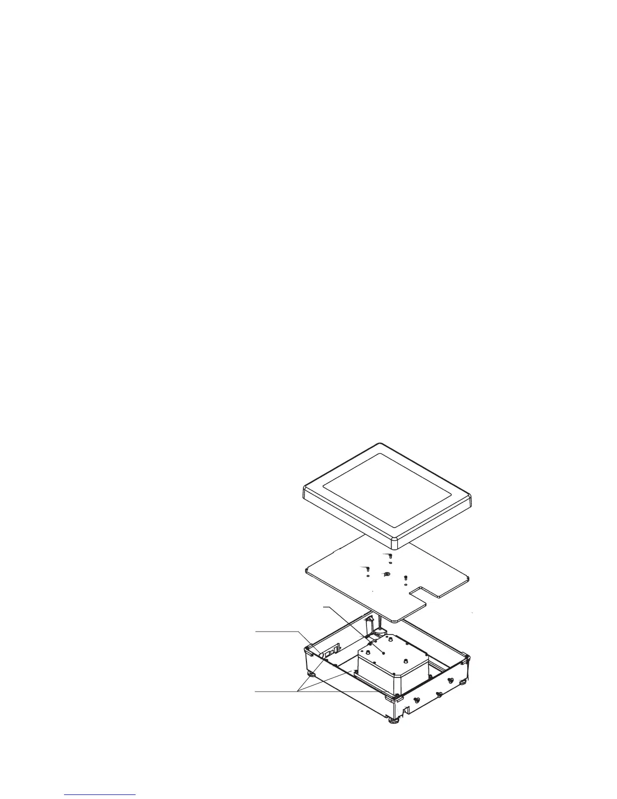
PAN
PAN SUPPORT
BASE
LOAD CELL
MODULE
Figure 1. Exploded view of Super II bef ore Remote Scale Option Installation
A
REMOTE CONNECTOR
PLUG
A
A
REMOTE OPTION A TO D
CIRCUIT BOARD
LOCATION
FRONT
Appendix D
Strain Gauge Load Cell Remote Scale
Option
Installation
Disassembly of the scale is required when installing the optional strain gauge load cell base analog to
digital signal conversion PCB.
1. Remove the pan and the pan support by removing the 3 screws marked “A” in Figure 1.
2. Pop out the round connector plug from the hole marked “Remote Base” on the back cover.
3. Locate the two threaded holes in the left side of the bottom of the base casting (as viewed from the front of the base). Start a 6-32 x 3/8”
screw into each of the holes and turn them two revolutions each.
4. Refer to Figure 2. Pick up the circuit board and bracket assembly and orient it so that the flange with two slots is downward and the 6-pin
DIN connector faces the back. Lift the coil cord upward to the left and insert the bracket assembly into the base casting between the coil
cord and the load cell assembly, so that the straight section of the cord is against the back edge of the bracket assembly above the DIN
connector (circuit board face the load cell assembly).
5. Slide the circuit board back until the bottom of the bracket touches the back of the base casting and then slide the bracket to the left so
that the flange slots slide around on the 6-32 x 3/8” screws. The coil cord should lie beween the bracket and the left side of the base
casting.
6. Tighten down the 6-32 x 3/8” screws to hold the bracket in place.
7. Connect the Strain Gauge Remote Scale Option circuit board cable to the 10 pin header between the two RJ-45 jacks on the Rear Power
Circuit Board.
8. Reinstall the pan and pan support with the 3 screws.
9. The scale is now ready for Remote Base calibration and operation.
 Loading...