Appendix D • Super II 117
Connector Wiring
If the cable connector of the remote scale base is physically compatible with the 6 pin circular DIN connec-
tor on the back of the Super II scale, proceed to Figures 4 and 5 to verify that it is electrically compatible.
Otherwise, damage may be caused to both the Super II scale and the remote scale base.
If the cable connector of the remote scale base is not compatible with the 6 pin circular DIN connector on
the back of the Super II scale, follow the procedures directly below.
NOTE: DISCONNECT THE SUPER II SCALE AND REMOTE SCALE BASE FROM ITS POWER SOURCE BEFORE
PERFORMING THE FOLLOWING PROCEDURES.
1. Remove the existing remote scale base connector.
2. Taking the connector supplied, separate the cord guard and metal housing by removing the screw.
3. Slide the metal housing onto the cable of the remote scale base. (See Figure 3.)
4. Strip 1/2" of the cable insulation.
NOTE: Do not nick, scrape or cut foil or braided shield when stripping cable insulation. Be equally
careful not to mar the wire insulation when stripping the shield or conductors when stripping the
wire insulation.
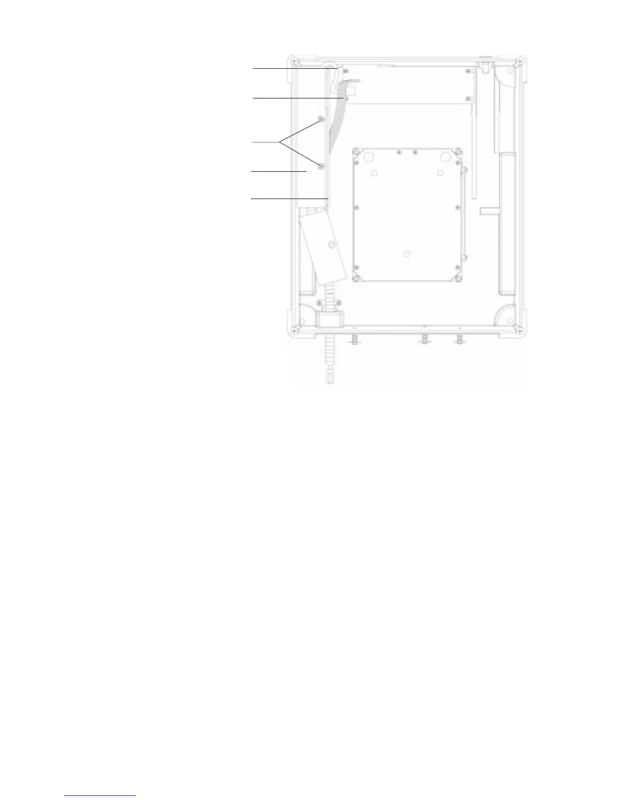
COIL CABLE
REMOTE SCALE OPTION
CIRCUIT BOARD CABLE
RSO MOUNTING SCREWS
RSO MOUNTING BRACKET
RSO CIRCUIT BOARD
.
.
.
.
Figure 2. Overview of Remote Scale Option Installation
FRONT OF SCALE
 Loading...