Appendix D • Super II 118
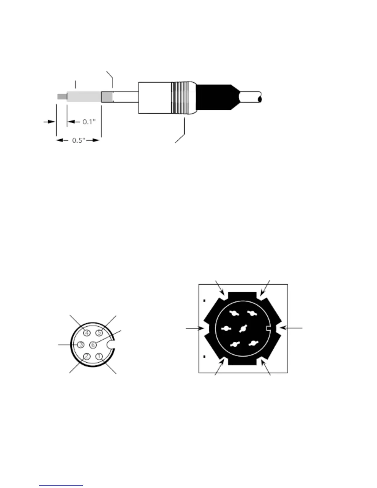
5. Fold back the shield and strip 1/10" from each wire.
Figure 3. Cable Preparation
6. Following the wiring diagram in Figure 4, solder each wire to the pin contact.
7. Make sure all of the wires do not make contact with each other, then crimp the plug extension to the shield of
the cable, solder to secure, if possible.
8. Slide the metal housing over the plug and secure with the screw using a small screwdriver.
Figure 5. 6 Pin circular DIN Connector on back o f Super II Scale
Figure 4. View from solder end o f
shielded DIN plug connector .
#4
- signal
#5
+ sens
#3
+ signal
#6
- sens
#1
+ exc
#2
- exc
Wires
Shield
Metal
Housing
- signal
+ signal
+ sens
- sens
+ exc
- exc
 Loading...