Do you have a question about the SEW-Eurodrive MOVIDRIVE compact MCV40A and is the answer not in the manual?
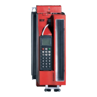
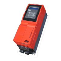
Detailed explanation of the unit and control functionalities of the MOVIDRIVE® compact drive inverters.
Technical data and dimension drawings for AC 400/500 V units, sizes 1-5.
Technical data and dimension drawings for AC 230 V units, sizes 1-4.
Technical data and selection guide for BW braking resistors.
Comprehensive list of all parameters with their setting ranges and factory settings.
Detailed explanation of individual parameters, grouped into 10 categories.
Describes the different operating modes available for MOVIDRIVE® drive inverters.
Guidelines for selecting asynchronous AC motors for VFC operating modes.
Recommendations for selecting asynchronous servomotors for CFC operating modes.
Guidelines for selecting synchronous servomotors for SERVO operating modes.
Explains how to determine the overload capacity of MOVIDRIVE® inverters.
Provides guidance and tables for selecting the appropriate braking resistor.
Details components and measures for EMC-compliant installation.
Core installation guidance including tightening torques and mounting positions.
Essential wiring diagrams for the power section, brake, and control unit.
Guidance on selecting and assigning braking resistors, chokes, and filters.
Guidance on connecting motor encoders and external encoders for feedback.
Basic steps and prerequisites for successful drive startup.
Step-by-step guide for performing startup using the DBG11B keypad.
Procedure for performing startup using a PC and the MOVITOOLS® software.
Detailed instructions on how to start the motor after initial configuration.
A comprehensive reference list of all inverter parameters and their settings.
Procedure for configuring and starting the inverter using PROFIBUS-DP.
Procedure for configuring and starting the inverter using INTERBUS.
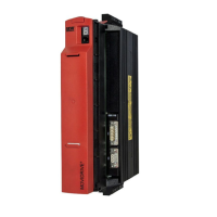
Explanation of the operating status indicated by the LEDs on MC_40A units.
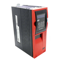
Explanation of the operating status indicated by the LEDs on MC_41A units.
Explanation of the operating status indicated by the LEDs on MCH42A units.
Instructions on using the DBG11B keypad for operation and parameter access.
Details on the fault memory and switch-off responses for troubleshooting.
A comprehensive list of fault codes, possible causes, and measures for resolution.
| Series | MOVIDRIVE compact |
|---|---|
| Type | MCV40A |
| Protection Class | IP20 |
| Storage Temperature | -25°C to +70°C |
| Relative Humidity | 5% to 95% (non-condensing) |
| Input Voltage | 380-500 V AC |
| Frequency Range | 0 to 400 Hz |
| Control Method | V/f control, vector control |
| Communication Interfaces | CANopen, PROFIBUS DP |
| Ambient Temperature | -10 °C to +50 °C |
| Installation Altitude | Up to 1000 m above sea level |