Do you have a question about the SEW-Eurodrive MOVIDRIVE system and is the answer not in the manual?
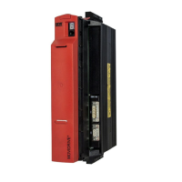
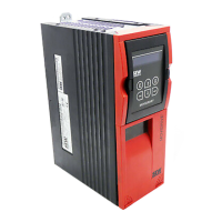
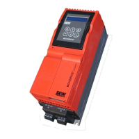
Product manual for MOVIDRIVE® system application inverters, covering drive technology, MotionControl, control technology, and visualization.
Explains Function Control Blocks (FCBs) for modular firmware, enabling selection/deselection of drive functions.
Describes available control modes: U/f, VFCPLUS, CFC, and ELSM® for MOVIDRIVE® inverters.
Provides detailed performance data, input/output specs, and dimensions for the basic device.
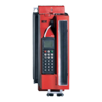
Introduces SEW-Workbench as central config software for inverters, detailing its key features.
Guides on selecting the correct drive considering machine data, conditions, and motor types.
Provides recommendations for motor selection based on thermal/dynamic curves and control modes.
Guides on selecting braking resistors based on continuous power, overload factor, and peak power.
Outlines user responsibilities for safety compliance and qualified personnel.
Specifies intended use in electrical plants/machines and relevant directives.
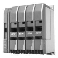
Describes connection variants for MOVIDRIVE® system with different MOVI-C® CONTROLLER types.
Emphasizes proper installation, cooling, protection from strain, and conductive mounting plates.
Covers electrical installation safety, handling voltages, protective separation, and grounding.
Discusses safety for braking resistors, including voltage, hot surfaces, and installation positions.
Offers recommendations for optimizing system electromagnetic compatibility and HF equipotential bonding.
Lists necessary hardware and software components for startup.
Details fault descriptions for the basic device, categorized by subfaults.
Describes faults related to the power section: DC link, temperature, processor, software, and device monitoring.
| Category | Inverter |
|---|---|
| Series | MOVIDRIVE system |
| Output Voltage | 0 - Input Voltage |
| Protection Class | IP20, IP65 (depending on model) |
| Type | Frequency Inverter |
| Output Current | Varies by model |
| Control Method | Sensorless vector control, V/f control |
| Communication Interfaces | CANopen |
| Safety | Safe Torque Off (STO), Safe Stop 1 (SS1) |
| Input Voltage | 200-240V AC, 380-480V AC, 500-600V AC |