EasyManuals Logo

SEW-Eurodrive MOVIDRIVE system User Manual

SEW-Eurodrive MOVIDRIVE system
384 pages
To Next Page IconTo Next Page
To Previous Page IconTo Previous Page
Page #263 background imageLoading...
Page #263 background image
8
Installation
EMC-compliant installation
Product Manual – MOVIDRIVE
®
system
263
8.10.4 Supply system cable connection
The supply system cable can be connected to the line choke and/or line filter using
twisted unshielded single conductors or using unshielded cables.
If necessary, shielded cables may improve EMC.
8.10.5 Line filter connection
Limit the length of the connection lead between the line filter and the inverter to the
absolute minimum needed.
You must never route filtered and unfiltered cables together. For this reason, route in-
coming and outgoing line filter cables separately.
8.10.6 Braking resistor connection
For connecting braking resistors, use two closely twisted cores or a shielded power
cable. In the case of shielded cables, connect the braided shields over the entire cir-
cumference. Use the designated shield plates at the basic device to connect the
shield.
19508521739
28487486/EN – 02/2019
8

Table of Contents

Other manuals for SEW-Eurodrive MOVIDRIVE system

Questions and Answers:

Question and Answer IconNeed help?

Do you have a question about the SEW-Eurodrive MOVIDRIVE system and is the answer not in the manual?
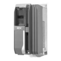
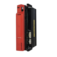
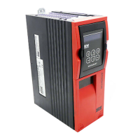
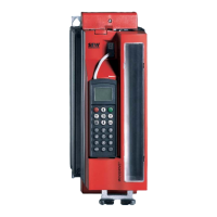
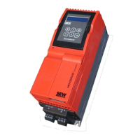
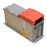
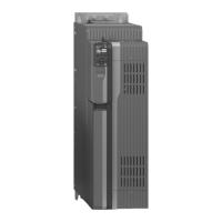
SEW-Eurodrive MOVIDRIVE system Specifications

General IconGeneral
CategoryInverter
SeriesMOVIDRIVE system
Output Voltage0 - Input Voltage
Protection ClassIP20, IP65 (depending on model)
TypeFrequency Inverter
Output CurrentVaries by model
Control MethodSensorless vector control, V/f control
Communication InterfacesCANopen
SafetySafe Torque Off (STO), Safe Stop 1 (SS1)
Input Voltage200-240V AC, 380-480V AC, 500-600V AC

Related product manuals