Do you have a question about the SFE SIATA and is the answer not in the manual?
Details on how to package and store the equipment, including temperature and humidity ranges.
Instructions for installing the equipment by specialized personnel in a dry place.
Guidelines for cleaning the equipment using a dry or damp cloth.
Provides technical specifications for the SFE controller, including power supply and protection rate.
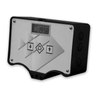
Details the buttons and their functions on the controller's front panel.
Explains the LCD display elements and their meanings during operation.
Explains the display indications during the regeneration cycle phases.
Provides an overview of programming modes and external signal handling.
Instructions on how to initiate manual regeneration and choose start options.
Describes display messages related to microswitch search attempts.
Explains how to recharge the salt counter after a salt alarm.
Details how to access and view historical data from the Statistics menu.
Procedure to reset the EEPROM to default values, excluding statistical data.
Describes how the module behaves during different types of power failures.
Guides through setting common operating parameters like time and regeneration days.
Details advanced parameters for regeneration start modes, intervals, and durations.
Illustrates various pre-set regeneration modes with their respective settings.
Details the 'SAL' error message indicating an empty brine tank.
Explains the 'Fr01' error message related to microswitch failure.
Instructions for installing the controller on SIATA V132 and V230 valves.
Details the installation process for the controller on SIATA V250 valves.
Lists spare parts for the twin pilot SFE controller.
| Brand | SFE |
|---|---|
| Model | SIATA |
| Category | Controller |
| Language | English |