GB
appendice
page 7
I D F E
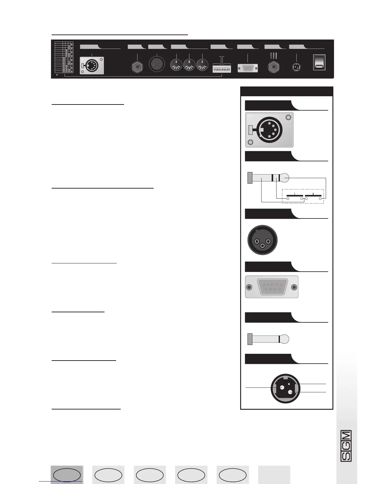
1.4 Studio 12 connectors
1.4.1 - DMX 512
Studio consoles have DMX 512 input/output. At present, the
input isn’t enabled by the software. Balanced 2 x 0.25mm
2
RS-
485 cables should be used for connection and must be good
quality to avoid faulty equipment operation.
Attention: cables’ screen (braid) must NEVER be connected to
the system’s ground, as this will cause faulty fixture and con-
troller operation.
1.4.2 - Up-down pedal
This socket allows a pedal to be connected to the console for
stepping up and down through the registers. Stepping is
between registers on the same page (see PAGE function). If UP
and DOWN are pressed simultaneously, the register is switched
off. Registers are enabled by pressing UP (starting with register
1) or DOWN (starting with register 12).
1.4.3 - SMPTE
The SMPTE signal allows operators to record series of events in
sync with an SMPTE time code. This ensures absolutely precise
sync, ideal for musical, television and theatre applications.
1.4.4 - MIDI
The Studio console has MIDI In, Thru and Out connections,
which offer a considerable amount of functions. See the relative
chapter for details.
1.4.5 - RS-232
By means of this connector, the console can be linked to a per-
sonal computer. This offer a remarkable amount of functions
(see the relative chapter for details).
1.4.6 - Audio in
This socket is used to enable all the music sync functions available on the console. When there’s
no direct connection to an audio source, the built-in microphones is used. A 0dB mono, signal
LINE signal is required. The left channel of a stereo signal can be used as an alternative.