11
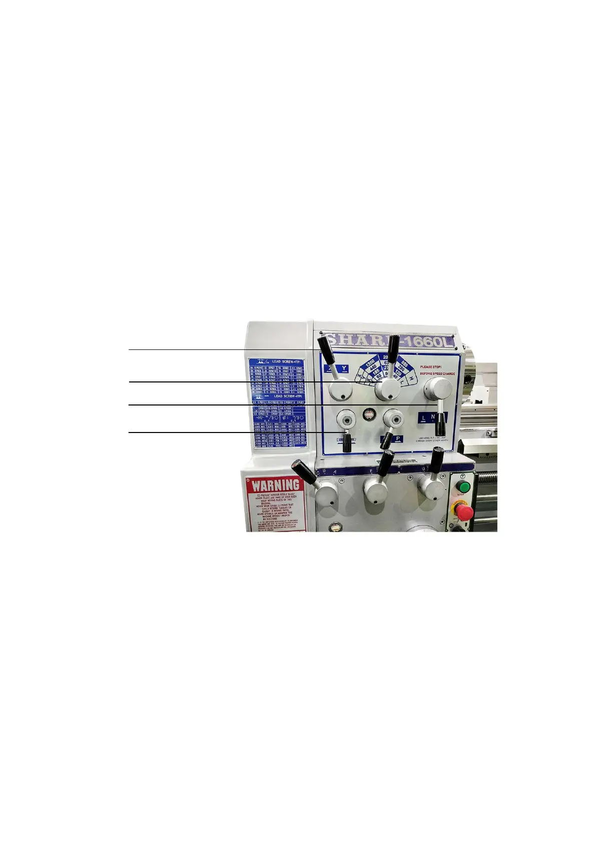
4-2 Transmission & Stop of Spindle
After the procedure described previously in this manual have been done, it is time
to test the machine.
Position the spindle H/L shifting lever ○
2
to “L”, the spindle speed shifting
selection lever ○
3
to the very left side, and forward/reverse shifting lever ○
4
to “N”
position. Lift the spindle operation control lever (○
11
of item 1-1), the spindle will
rotate forward, press down the lever, the spindle will rotate reverse; in ‘Neutral’
position, the spindle will stop. For normal forward & reverse revolution, always
operate the spindle operation control lever. For emergency stop, step on the foot brake,
the spindle operation control lever should push back to ‘Neutral’ position after
stepping the foot brake. Afterward, start the spindle.
Turn the coolant supply button (○
10
of item 1-1). Adjust the adjusting valve for
the required coolant flow.
Fig.4-2
4-3 Spindle Speed Selection
Spindle speed shift is made up of three speed shifting levers:
1. Spindle speed shifting lever
2. Spindle speed H/L shifting lever
3. Spindle speed shifting selection lever for total of 12 spindle speed numbers
Put the spindle speed H/L shifting lever to ‘neutral’ gear between ‘H’ and ‘L’
rotate the spindle by hand.
For safety and protecting the gears from damage, only change speeds when the motor
is completely stopped. If the gears are not easily engaged, press intermittent button
and handle the speed shifting levers to change the speeds.