Main Sub
Item Content
Adjustment
code code range
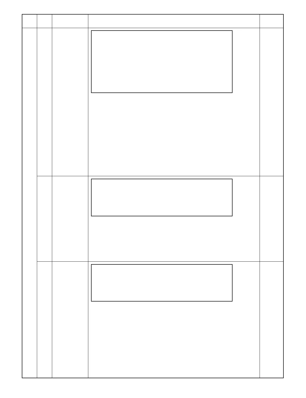
44 01 Sets each mode
of process
control.
0-3SIMULATION NO.44- 1
PROCESS CONTROL MODE SETUP[X]:_
PROCESS DRUM
CONTROL ADJUSTMENT
0. OFF OFF
1. ON OFF
2. OFF ON
3. ON ON
INPUT SETUP VALUE AND PRESS PRINT SW
[Content] The current setting of process control is displayed and a new setting can be set.
After the execution of the simulation, the screen returns to the sub code input
screen.
(a) Operation/display
[PRINT]: If the entered value is valid, the current setting in brackets is updated. If the
entered value is not valid, the entered value is cleared and the error buzzer
sounds. If the [PRINT] key is pressed without entering any new setting, the
current setting is not updated.
[0-3]: Enters new settings
[C]: Clears the entered value.
[PAUSE]: The execution of the simulation is stopped and the screen returns to the
sub code input screen.
[CA]: The execution of the simulation is stopped and the simulation is terminated.
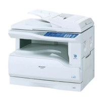
02 Adjusts DM
sensor.
SIMULATION NO.44- 2
DM SENSOR ADJUSTMENT
SENSOR RESPONSE:XXX
[PAUSE]KEY:END DISPLAY
[Content] The main motor/drum motor rotate for 3 minutes and the output value of the drum
marking sensor is displayed. Adjust the VR1 inside the process control unit so that
the output value is 210 ±30. After the execution of the simulation, the screen returns to
the sub code input screen.
[PAUSE]: The execution of the simulation is stopped and the screen returns to the
sub code input screen.
[CA]: The execution of the simulation is stopped and the simulation is terminated.
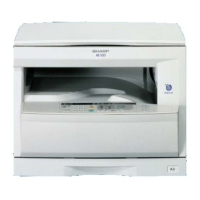
03 Adjusts ID
sensor.
SIMULATION NO.44- 3
ID SENSOR ADJUSTMENT
SENSOR RESPONSE:XXX
[PAUSE]KEY:END DISPLAY
[Content] The image density sensor gain is selected, the main motor/drum motor rotate for 3
minutes. The output value of the image density sensor is displayed. Adjust the
VR2 inside the process control unit so that the output value is 210 ±30. After the
execution of the simulation, the screen returns to the sub code input screen.
(a) Operation/display
[PAUSE]: The execution of the simulation is stopped and the screen returns to the
sub code input screen.
[CA]: The execution of the simulation is stopped and the simulation is terminated.
9 – 62