LC-52/60/70LE640U/C6400U,LC-80LE633U/844U (1st Edition)
4 – 26
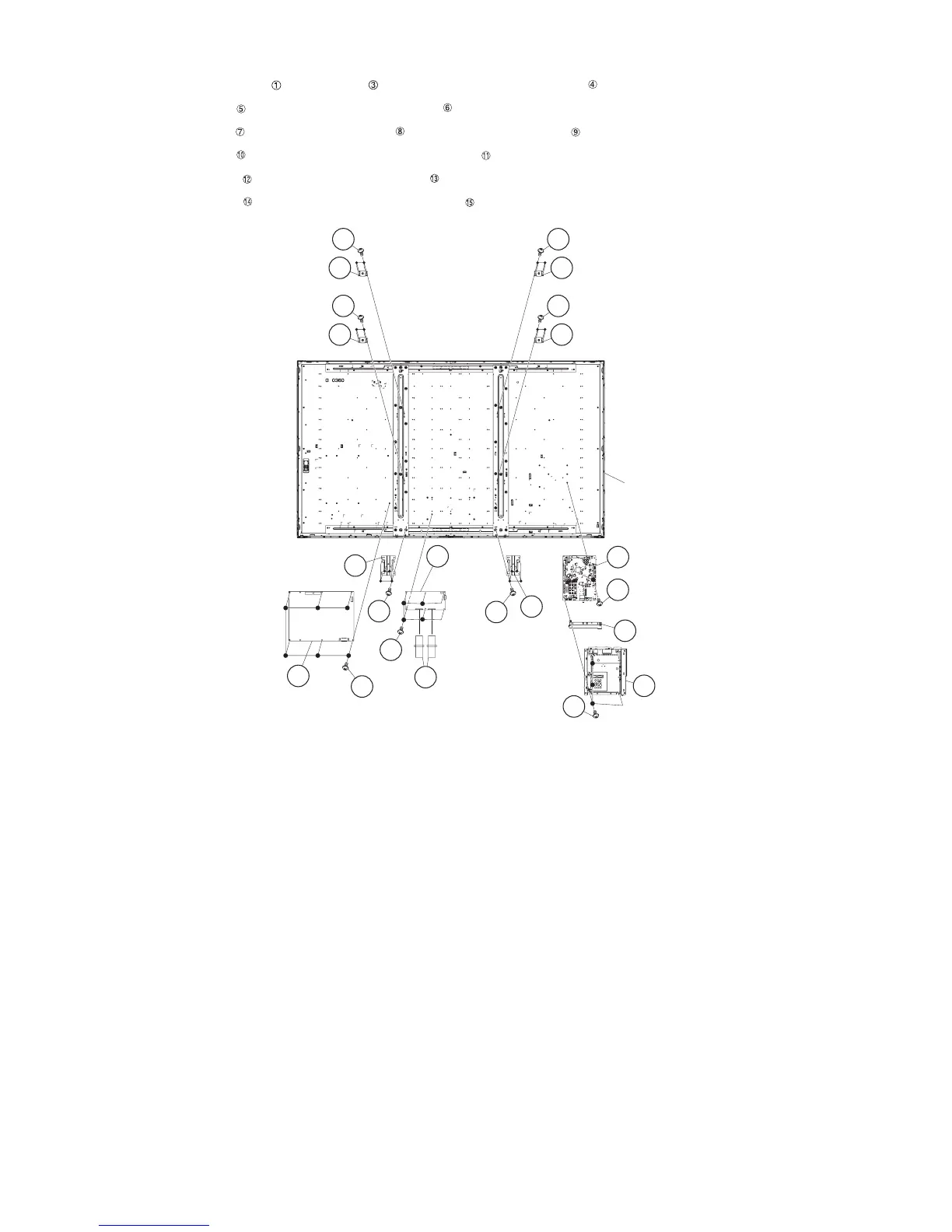
4. Removing of LCD CONTROL Unit, MAIN Unit, POWER/LED DRIVE Unit.
1. Remove the 2 Connecting Cords , 6 lock screws and detach the LCD CONTROL Unit .
2. Remove the 5 lock screws and detach the Shield (MAIN Unit) .
3. Remove the 3 lock screws and detach the MAIN Unit and Terminal Angle (Bottom) .
4. Remove the 6 lock screws and detach the POWER/LED DRIVE Unit .
5. Remove the 12 lock screws and detach the 2 Stand Angles .
6. Remove the 16 lock screws and detach the 4 VESA Angle Ass’ys .
80" LCD Panel
Module Unit
11
10
1 FFC
LCD
Control
Unit
12
3
13
12
POWER/
LED DRIVE
Unit
Stand Angle
13
Stand
Angle
8
5
4
Terminal
Angle
(Bottom)
7
Shield
(MAIN Unit)
6
MAIN Unit
9
14
15 VESA Angle Ass'y
14
15 VESA Angle Ass'y
14
15VESA Angle
Ass'y
14
15VESA Angle
Ass'y