l
Setting the test mode
Any one of 4 test modes can be set by pressing several keys as follows
<MEMORY>
+
<CD>
+
<POEER>
TEST
:
CD operation test
TEST
MODE
l
TEST 4 mode
Function
-
CD test mode
Setting of TEST 4 mode
k&cation
of CD TST mode (All LCD lights)
ObEN/CLOSE operation is manual operation.
1
IL is not performed.
T<e
pickup can be moved by using the
(w)
or
(+)
key.
1
t
<MEMORY>
<STOP>
<MEMORY>
<STOP>
When the tracking servo is
-
The pickup returns to the
-
When the tracking servo is
-
The pickup returns to the
turned on, PLAY is started at
ordinary stop position.
turned off, PLAY is started
ordinary stop position.
once.
at once.
L
<PLAY> key input
-
TOC. IL is performed, and the ordinary PLAY is performed.
-
Press
<STOP>
key.
-
Stop
If the following key is pressed during PLAY, it is possible to
specify directly any Track No.
<Disc
Number
l>
key: Track 3
<Disc Number
2>
key: Track 8
Note:
<Disc
Number
3~
key: Track 15
Only in STOP state it is possible to slide the pickup with the
(m)
or
(4q)
key.
VOL. --- Last memory
BAC.--- CENTER
R.GEQ.
--- FLAT
*
X-BASS --- OFF
Canceling method
-
POWER OFF
CD
SECTION
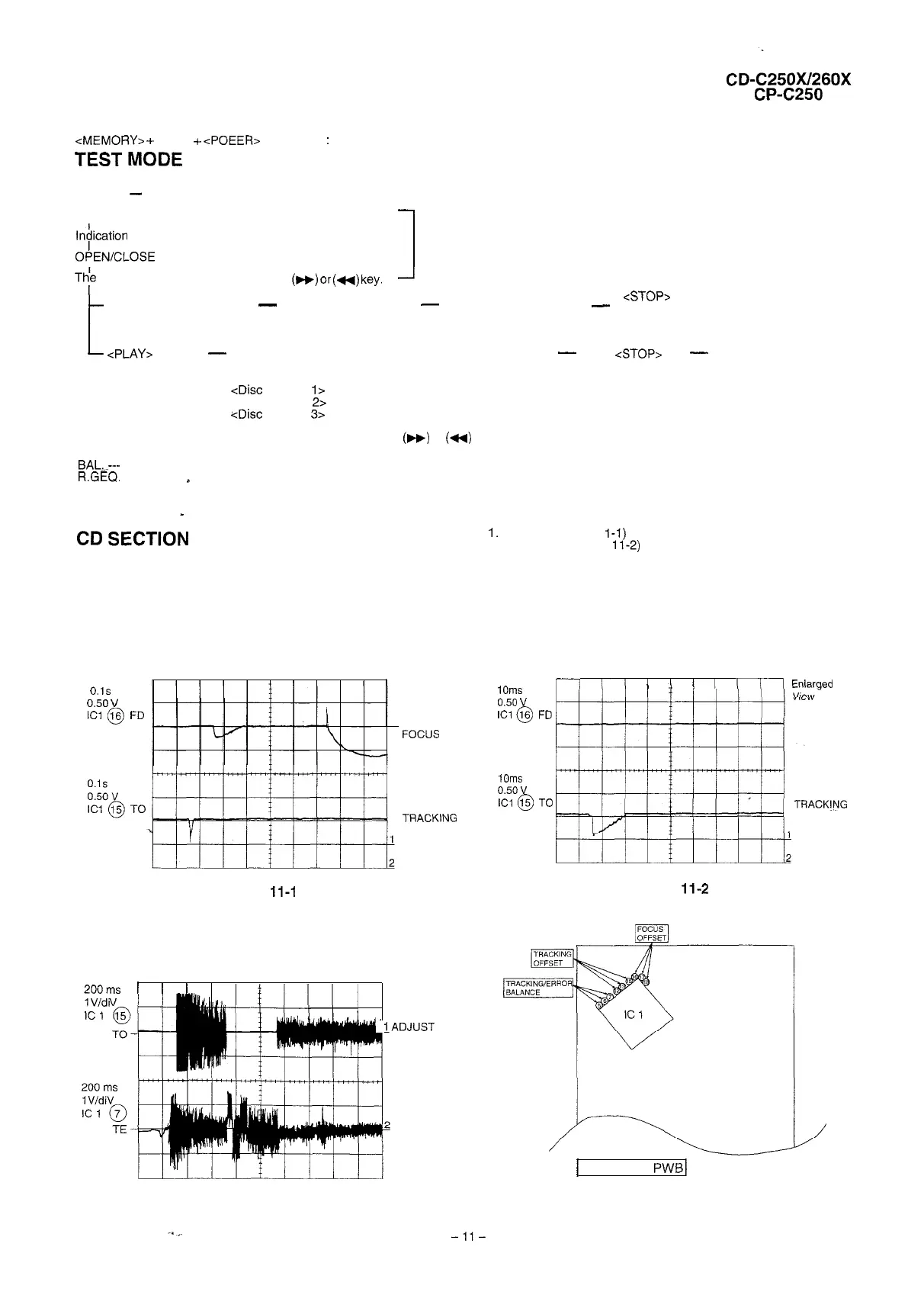
1.
Focus offset (Fig. 1
l-l)
2. Tracking offset (Fig.
11-2)
Since this CD system incorporates the following automatic adjustment
function, when the pickup is replaced, it is not necessary to readjust it.
3. E/F balance (tracking error balance) (Fig. 11-3)
4. RF level AGC function (HF level: constant)
5. RF level automatic follow-up of the tracking gain
l
Automatic adjustment item
This automatic adjustment is performed each time a disc is changed.
Therefore, each disc is played back using the optimal settings.
0.1s
0.50
v
tci
@
FD
TO
Figure 11-l
FOCUS
OFF-SET
ADJUST
TRACKlNG
OFF-SET
ADJUST
200
ms
I I I
TRACKING/
1Vidi
ERROR
IC
1
BARANCE
‘.
IADJUST
TE
/
CD SERVO
PWB
/
Figure 1 l-3
Figure 11-4 CHECKING POINTS
1Oms
0.50
v
ICl
@
1Oms
0.50
v
ICI
@
II
II’
1
I
Ill1
I
I
Enlaraed
“11””
FD
TO
TRACK!NG
OFF-SET
ADJUST
Figure
11-2
-ll-