FUNCTION
TABLE
OF
IC
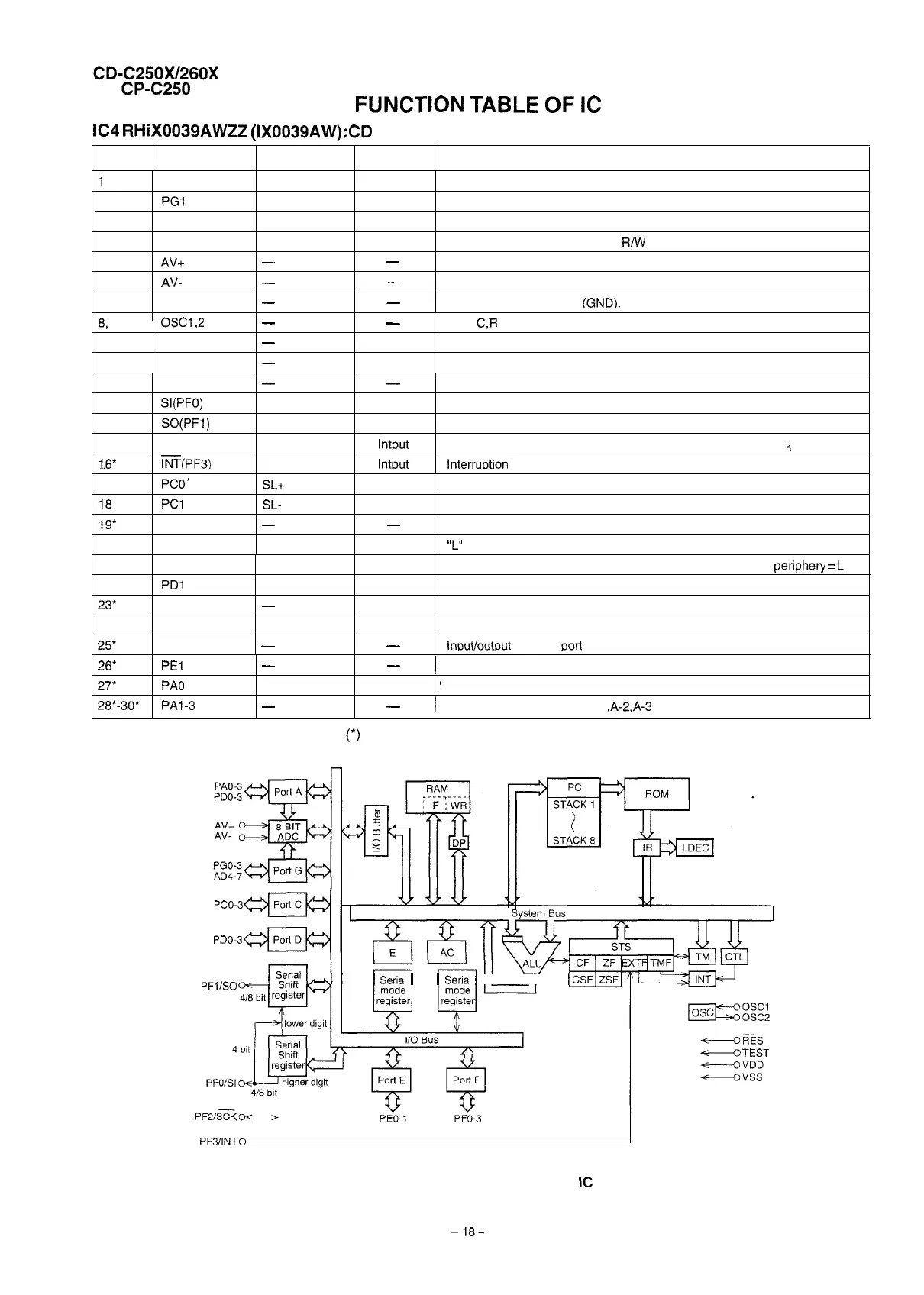
IC4
RHiX0039AWZZ (IX0039AW):CD Control Microcomputer
Pin No. Port Name
Terminal Name input/Output
Function
1
PGO
SQOUT
Input
Servo/signal control data input
2
PGl
COIN
output
Servo AMP, servo/signal control command output
3
PG2 CQCK
output
Servo AMP, servo/signal control clock output
4
PG3
RWC
output
Servo AMP, servo/signal control
R/W
control
5
AV+
-
-
Connect to AD converter reference voltage input terminal GND.
6 AV-
-
-
Connect to AD converter reference voltage input terminal GND.
7
vss
- -
Connect to VSS terminal
IGND).
8,
9
’
osc1,2
-
-
10
VDD
-
Input
11
RES
-
Input
OSC
C,R
or ceramic oscillator
Power terminal
Reset
12
13
14
15
1.6*
TEST
-
-
Test
SI(PF0)
COMM Input
Serial data input from main microcomputer
SO(PF1)
DATA
output
Serial data output from main microcomputer
SCK(PF2)
SCK
lntput Clock input from main microcomputer
5
-
INT(PF3)
lntout lnterruotion reauest terminal
17 PCO”
SL+
output Servo AMP slide feed output
16 PC1
SL-
output
Servo AMP. slide return output
19*
PC2
-
-
Input/output common port C-2
20
PC3 LASER
output
“L”
when laser is on
21 PDO
22
PDl
23* PD2
24
PD3
25*
PEO
PU-IN SW
Input
DRF
Input
-
input
WRQ
Input
-
-
Pickup internal periphery position detection input; innermost periphery
=
L
Servo AMP. RF detection input
Input/output common port D-2
Servo/signal control request
lnoutloutout
common
oorl
E-O
26*
PEl
-
-
/
Input/output common port E-l
27* PA0
RES
output
’
Servo/signal
control reset output
26*-30*
PAl-3
-
-
1
Input/output common port A-l
,A-2,A-3
In this unit, the terminal with asterisk mark
(*)
is (open) terminal which is not connected to the outside.
PCO-3
PDO-3
PFl/SO
I
I
Serial
I I
Serial
I
I I
l-r
Its
.
-TEST
Figure 18 BLOCK DIAGRAM OF
IC
-16-