CD-MD3000H/CD-MD3000W
– 18 –
Figure 18-1
Figure 18-2
1 Top Cabinet 1. Screw ................ (A1) x5 16-1
2 Side Panel
(Left/Right)
1. Screw ................ (B1) x8 16-1
3 Rear Panel 1. Screw ................ (C1) x3 16-2
2. Screw ................ (C2) x8
(For CD-MD3000H)
2. Screw ................ (C2) x7
(For CD-MD3000W)
4 Front Panel 1. Flat Cable.......... (D1) x1 16-2
2. Screw ................ (D2) x4
3. Socket ............... (D3) x6
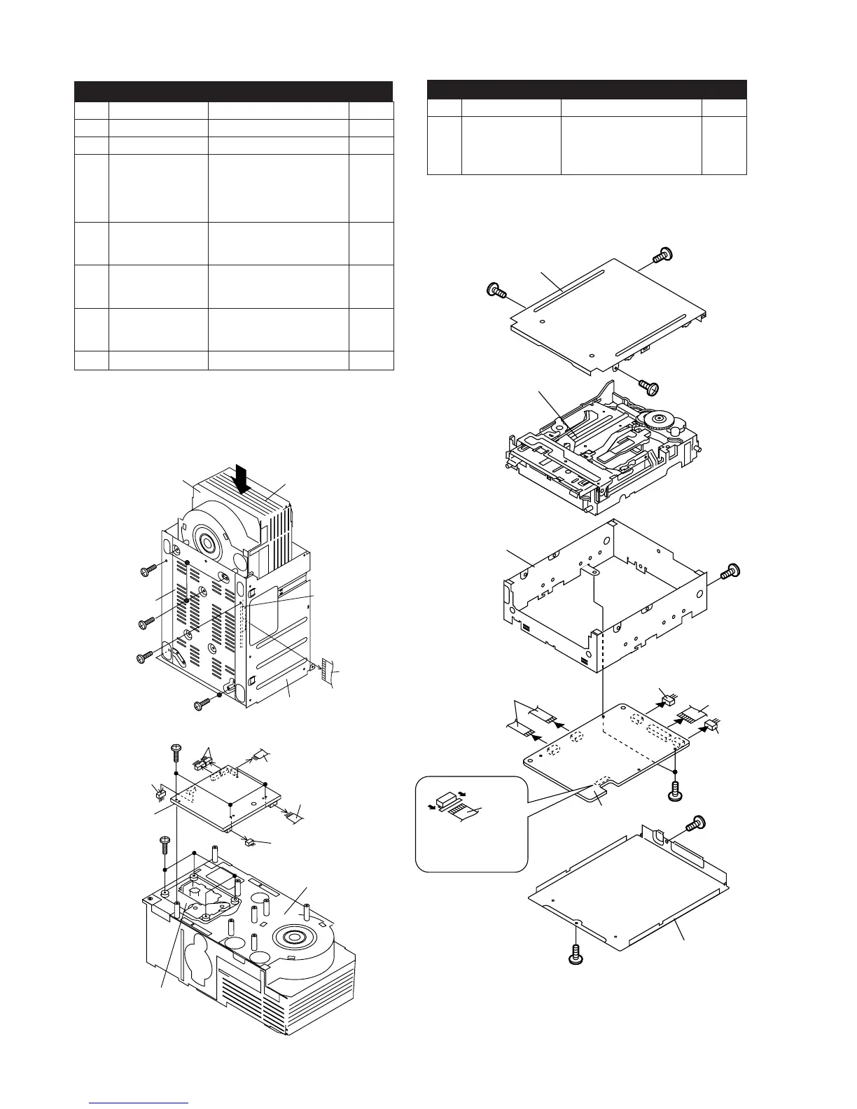
5 CD Changer 1. Flat Cable.......... (Y1) x1 18-1
Mechanism 2. Screw ................ (Y2) x2
3. Screw ................ (Y3) x5
6 CD PWB 1. Screw ................ (Z1) x4 18-2
(Note) 2. Socket ............... (Z2) x4
3. Flat Wire ............ (Z3) x2
7 CD Mechanism 1. Screw ................ (ZZ1) x4 18-2
STEP
REMOVAL PROCEDURE
FIGURE
CD-MD3000H/CD-MD3000W (CD CHANGER MECHANISM UNIT)
Note:
After removing the connector for the optical pickup from the
connector, wrap the conductive aluminium foil around the
front end of connector remove to protect the optical pickup
from electrostatic damage.
1 MD Mechanism/ 1. Screw ............ (AA1) x8 18-3
MD Main PWB 2. Flat Cable...... (AA2) x3
3. Flexble PWB . (AA3) x1
4. Socket ........... (AA4) x2
STEP REMOVAL
PROCEDURE
FIGURE
CD-MD3000H/CD-MD3000W (MD MECHANISM)
(Y3)x3
ø3x10mm
(Y2)x1
ø3x10mm
Bottom Side
Slide it in the direction of the arrow
after removing the screw (Y2).
Front Side
(Y2)x1
ø3x10mm
(Y3)x2
ø3x10mm
Main Chassis
CD PWB
(Y1)x1
CD Changer
Mechanism
(Z1)x4
ø3x10mm
(Z3)x1
(Z2)x1
(Z2)x1
(Z3)x1
(Z2)x2
(ZZ1)x4
ø2.6x10mm
CD PWB
CD Changer
Mechanism
CD Mechanism
(AA2)x2
(AA1)x1
ø2x2mm
(AA1)x1
ø2x3mm
(AA1)x1
ø2x3mm
(AA1)x1
ø2x3mm
(AA)x1
ø2x3mm
(AA2)x1
(AA4)x1
(AA4)x1
(AA1)x1
ø2x3mm
(AA1)x2
ø1.7x3mm
(AA3)x1
Pull
Pull
MD Main PWB
MD Mechanism
Shield Case,Side
Shield Case,Top
Shield Case,Bottom
Optical pickup
Flexible PWB
(Note 1)
(Note 1) After removing the flexible PWB for optical pickup
from the connector wrap the front end of flexible PWB in
conductive aluminum foil so as to protect the optical pickup
from being damaged electrostatically.
Note:
After removing the connector for the optical pickup from the
connector, wrap the conductive aluminium foil around the
front end of connector remove to protect the optical pickup
from electrostatic damage.
Figure 18-3