– 25 –
CD-MD3000H/CD-MD3000W
31
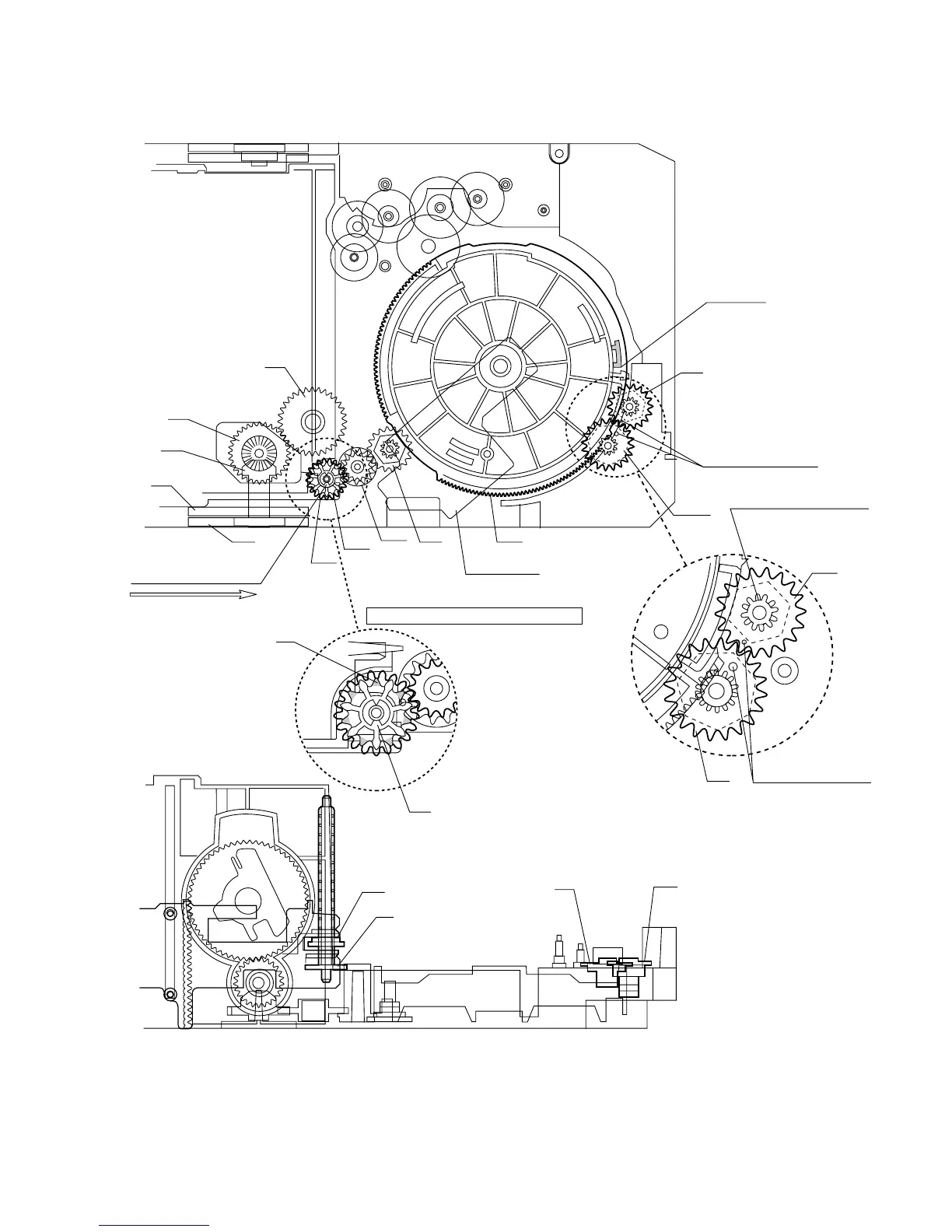
M T SW PWB
33
TRAY
GEAR B
32
TRAY GEAR A
33
TRAY GEAR B
37
32
TRAY GEAR A
38
34
TRAY DRIVE GEAR R
36
TRAY JOINT GEAR R
47
46
34
TRAY DRIVE GEAR R
36
TRAY JOINT GEAR R
10
29
29
23
23
24
25
26
27
Mark position
11
45
TRAY BIG GEAR SET POSITION
33
32
Direct the recess part
(trapezoidal side) of the axis
35 in this direction.
* This position becomes the
reference (stock) position
of the tray.
These holes must align.
It must not rotate in contact
with the peripheral (hatched)
part of 31.
These holes must align.
After assembling 32,
assemble 33.
*1: To position the axis part of 36, engage it with 38.
*2: When it is aligned as described in *1, the hatched part
(low gear-height part of gear) will be positioned in this position.
Note: After positioning the tray big gear in the set position, engage these gears.
*1
*2
Scale: 2 magnifications
Scale: 2 magnifications
Figure 25