CD-MD3000H/CD-MD3000W
– 42 –
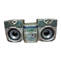
Figure 42-3 Optical Pickup Grating Deviation
Measuring Method
Mechanism Adjustment
1. Optical pickup grating inspecting method
After auto adjustment (COMPLETE appears) in the test mode (auto)
using the high reflection MD disc TGYS1, adjust the Lissajou's
waveform (x-y) of EOUT to FOUT.
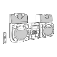
1. Slightly loosen the 3 screws of the spindle motor, adjust while
observing the Lissajou's waveform.
2. After adjustment, tighten screws 1, 2, and 3 in numerical order.
(See Fig. 42-4.)
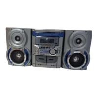
Lead-in switch position measurement mode
Insert the high reflection test disk TGYS1.
Note: Adjust the lead-in switch position within the range of FF85 -
FFD2.
1. Measure the lead-in switch position. Loosen the screw (A1) x 1 pc.
which fixes the mechanism switch PWB.
2. When the lead-in switch is located FF85 or less, tighten the screw
while pressing the PWB in the direction of the arrow A. When FFD2
or more, to direction B. Measure the lead-in switch position again.
After position adjustment is completed, fix the PWB with the screw
(A1) x 1 pc.(shown in Figure 42-1)
Figure 42-1
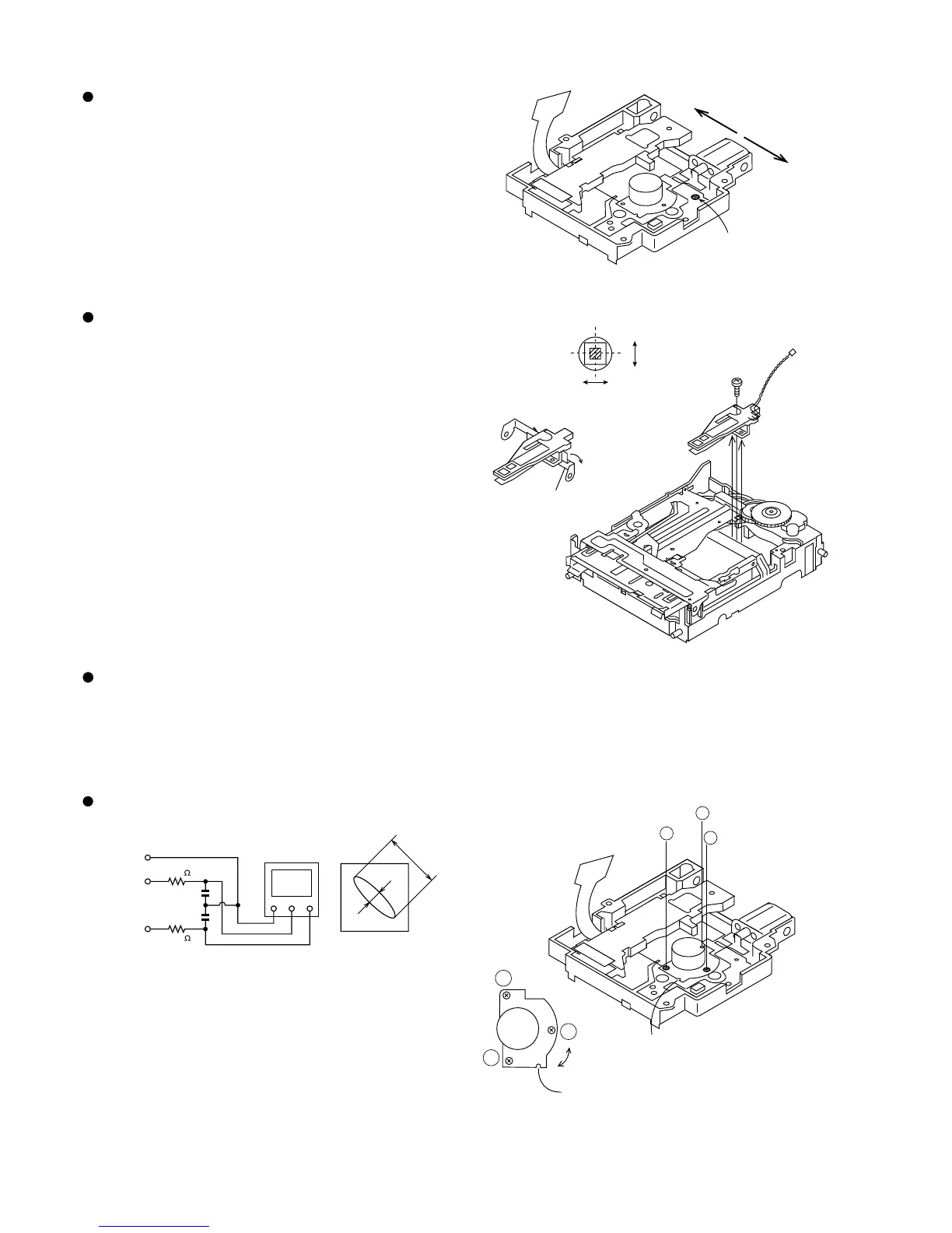
Rotating the loading motor forcibly
The loading motor can be rotated forcibly by rotating the JOG UP/
DOWN knob while STOP or EJECT in the test mode appears on the
display.
Figure 42-2
Figure 42-4
Magnetic head mounting position check
• Check the mounting position whenever the magnetic head and the
optical pickup are replaced.
• Move the optical pickup to the center to adjust the position easily.
1. Set the adjusting transparent disc 3.
2. Press down the magnetic head up shift arm by hand to raise the
magnetic head.
3. View the set from above to check whether the magnetic head aligns
with the optical pickup objective lens.
4. Check that the magnetic head moves up and down smoothly.
(shown in Figure 42-2)
A
B
(A1) X1
Magnetic head
Objective lens
Radiai
Head up- shift arm
Tangential direction
2
3
1
2
3
1
adjusting
hole
Check the Lissajou's waveform,
shifting the mounting position with
a screwdriver (to be fitted into the
disc motor adjusting hole).
OSILLOSCOPE
GND CH1 CH2
XY
4 Pin of IC1201
GND (TP1202)
11Pin of IC1201
EOUT (TP1253)
12 Pin of IC1201
FIN (TP1253)
100K
470p
470p
a
b
LISSAJOUS'S WAVEFORM
Less than a:b = 4:1
100K