CD-SW330
3 – 5
2. CHANGER MECHANISM SECTION
Perform steps 1, 2, 3, 13, 14, and 15 of the disassem-
bly method to remove the CD changer mechanism.
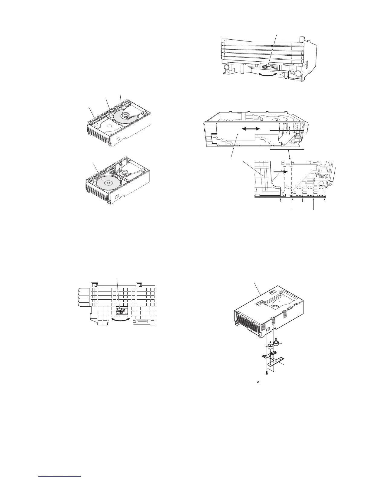
2.1. How to remove CD Disc (See Fig. 1~4)
1. When CD is at play position (Figure1), rotate reduc-
tion gear C clock-wise as shown in Figure 2 Until
disc tray is at stock position, then rotate further to
eject the disc tray so that CD can be removed from
the tray.
Figure 1
Figure 2
2. In another case, if CD mechanism is at tray No.1
play position and to remove CD located in tray No.3,
the procedure is as follows:
If the gear up down board is located at tray No.1
position, then rotate gear clock-wise until it at stock
position. Rotate reduction gear D clockwise (Figure
3) to move the CD mechanism to tray No.3 posi-
tion.This is confirmed by checking the gear up down
board position by the marking as indicated on the
main chassis as shown in Figure 4.
Figure 3
Figure 4
2.2. How to Remove the tray motor/main cam
motor/5-Changer Motor PWB (See Fig. 5)
1. Remove the screws (A1) x 2 pcs., to remove tray
motor/main cam motor/5-Changer Motor PWB.
Figure 5
NOTE: There are 2 more screws tighten the motors at
the bottom of main chassis. Before performing
procedure 1 above, disc stop spring, top plate
gear up down board and trays must be
removed, then only the 2 screws can be
untighten.
CD Disc
CD Disc
CD at play position.
Disc Tray
Guide Tray
CD at STALK position.
Reduction gear C
Front Rear
Reduction gear D
Up Down
Mark 1
(DISC 1)
(DISC 2)
(DISC 3)
(DISC 4)
(DISC 5)
Gear up down board
Mark 3 Mark 5
Mark 2 Mark 4
5-Changer
Motor PWB
Tray Motor
Changer Mechanism Unit
Main Cam Motor
(A1)X2
2x10mm