– 13 –
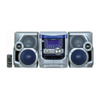
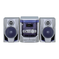
CD-XP120W
• The indicated voltage in each section is the one measured
by Digital Multimeter between such a section and the chas-
sis with no signal given.
1. In the tuner section,
indicates AM
indicates FM stereo
2. In the main section, a tape is being played back.
3. In the deck section, a tape is being played back.
4. In the power section, a tape is being played back.
5. In the CD section, the CD is stopped.
• Parts marked with “ 1 ” ( ) are important for
maintaining the safety of the set. Be sure to replace these
parts with specified ones for maintaining the safety and
performance of the set.
NOTES ON SCHEMATIC DIAGRAM
• Resistor:
To differentiate the units of resistors, such symbol as K and
M are used: the symbol K means 1000 ohm and the symbol
M means 1000 kohm and the resistor without any symbol is
ohm-type resistor. Besides, the one with “Fusible” is a fuse
type.
• Capacitor:
To indicate the unit of capacitor, a symbol P is used: this
symbol P means pico-farad and the unit of the capacitor
without such a symbol is microfarad. As to electrolytic
capacitor, the expression “capacitance/withstand voltage”
is used.
(CH), (TH), (RH), (UJ): Temperature compensation
(ML): Mylar type
(P.P.): Polypropylene type
• Schematic diagram and Wiring Side of P.W.Board for this
model are subject to change for improvement without prior
notice.
REF. NO DESCRIPTION POSITION
SW703 TUNING UP ON—OFF
SW704 PRESET UP ON—OFF
SW705 TUNER (BAND) ON—OFF
SW706
TUNING DOWN
ON—OFF
SW707 PRESET DOWN ON—OFF
SW708 EQUALIZER/X-BASS/DEMO ON—OFF
SW709 TAPE ON—OFF
SW710 STOP ON—OFF
SW711 VOLUME UP ON—OFF
SW712 DISC SKIP ON—OFF
SW713 OPEN/CLOSE ON—OFF
SW714 PLAY/REPEAT ON—OFF
SW715 VOLUME DOWN ON—OFF
SW801 REC./P.B. ON—OFF
SW1 OPEN/CLOSE ON—OFF
SW2 DISC ON—OFF
SW3 UP ON—OFF
SW4 PICKUP IN ON—OFF
SW5 TAPE 1 PLAY ON—OFF
SW6 TAPE 1 FF/REW ON—OFF
SW7 TAPE 2 FF/REW ON—OFF
SW8 TAPE 2 PLAY ON—OFF
SW101 VOLTAGE SELECTOR 110 V—127 V—
220 V— 230-240 V
SW102 SPAN SELECTOR 50 kHz/9 kHz—
100 kHz/10 kHz
SW701 ON/STAND-BY ON—OFF
SW702 CD ON—OFF
TYPES OF TRANSISTOR
REF. NO DESCRIPTION POSITION
(1) (2) (3)
(S) (G) (D)
E C B
FRONT
VIEW
B C E
FRONT
VIEW
KRA102 M
KRC102 M
KRC107 M
KRC104 M
KSA1015 GR
KSA1815 GR
HSB562 C
HSC1609 GR
KSC1815 GR
KSC3203 Y
KSA1271 Y
SSC1674 C
2SD2012 Y SD3210W
FRONT
VIEW