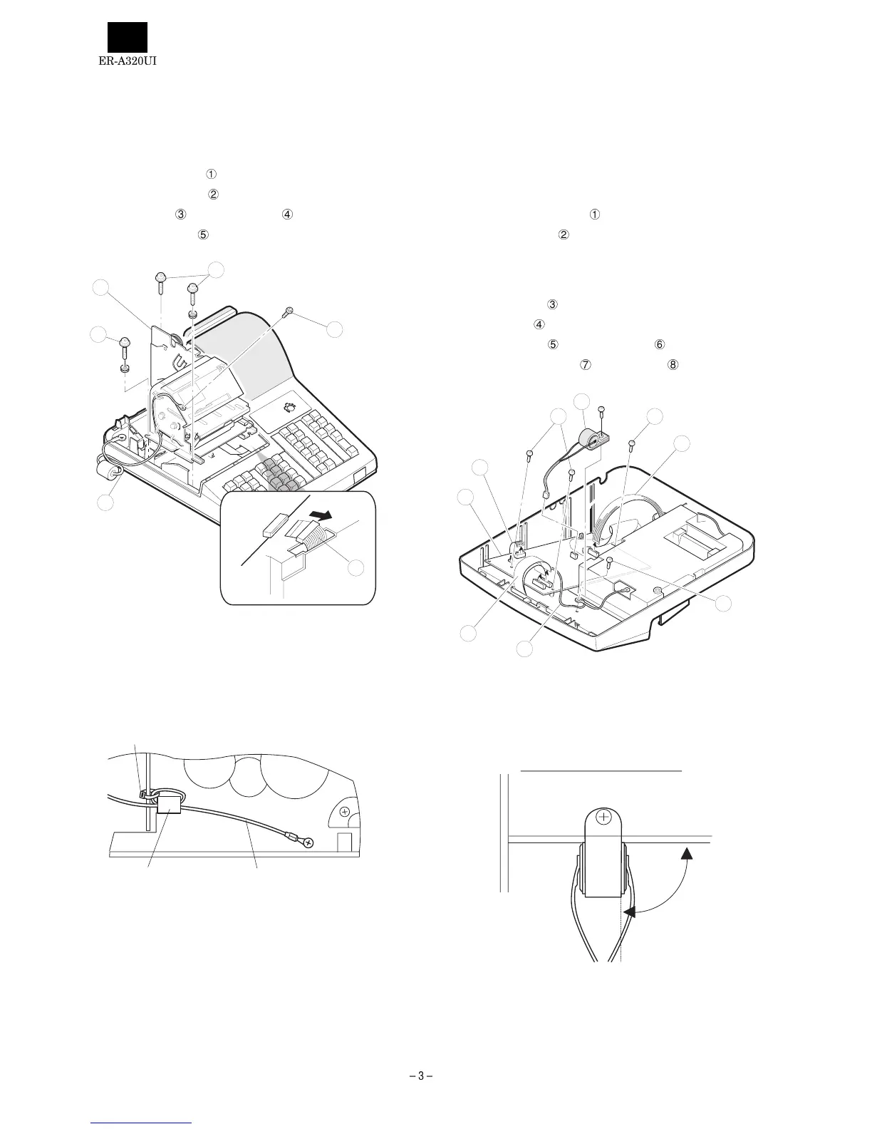
CHAPTER 4. REMOVING THE
PRINTER UNIT
1) Remove the top cabinet.
2) Remove the printer cable
from the main PWB.
3) Remove the three screws
.
4) Remove the screw
and grounding wire .
5) Remove the printer unit
from the top cabinet.
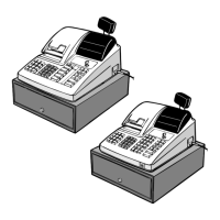
Caution to be taken when replacing the printer unit
Make sure to perform the following procedure when installing the core
to the grounding wire at the right side (when looking from the front
side) of the printer unit.
· View looking from the right side of the printer unit.
Wind the grounding wire around the core by a turn and secure to the
printer frame with the nylon band.
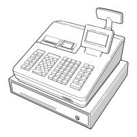
CHAPTER 5. REMOVING THE MAIN
PWB
1) Remove the top cabinet.
2) Remove the printer unit.
3) Remove the following connector cables from the main PWB.
Rechargeable battery cable
Pop-up display cable
Note: The pop-up cable is fixed with the holder not to make con-
tact with the heat radiating plate on the main PWB. Be
careful of it when installing.
Mode switch cable
Keyboard cable
4) Remove the screw and grounding wire .
5) Remove the three screws
and main PWB .
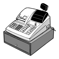
Caution to be taken when installing the battery
To prevent the battery from shorting due to water that might be
splashed on the printer cover or the keyboard, install the battery at an
angle of 90° in relation to the keyboard.
1
3
4
5
2
2
Core
Grounding wire
Nylon band
8
3
77
2
5
4
6
1
90°