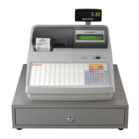
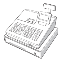
ER-A520U/ER-A530U HARDWARE DESCRIPTION
– 13 –
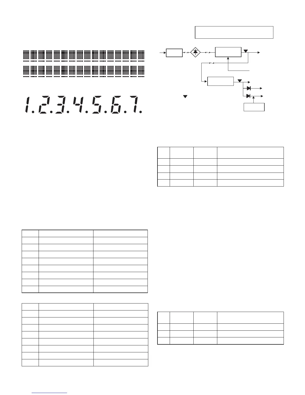
6-3. DISPLAY
The ER-A520/530 is provided with the LCD display of 5 x 7 dot, 2 line,
16 digit on the FRONT side, and the LED display of 7 digit on the POP
UP side.
FRONT:
POP UP:
• DISPLAY DIGIT SIGNAL
The above ST0~ST6 are DIGIT signals.
ST0:1st digit~ST6:7th digit
• DISPLAY SEGMENT SIGNAL
The LED segment signal can be outputted by writing segment data
to 4000h.
DATA~SEGMENT assignment
7. SERIAL I/O
The ER-A520/530 is provided with 2ch RS-232 ports as standard provi-
sion.
Ch1 and Ch2 of RS-232 are assigned to the following CPU ports.
Ch1
Ch2
8. POWER
9. FLASH MEMORY REWRITE PROCEDURE
The FLASH ROM of Fujitsu MBM29F800TA-90 is employed.
IPLONO# :"1"; IPL from EP-ROM. Executed from ER ROM.
IPLON1# :"1"; IPL from COM
WP#: Write protect signal of FLASH ROM. "0" write protect. Not used
in the ER-A520/530.
RY/BY# : Ready/Busy signal from FLASH ROM
IPL from EP-ROM : After setting the IPL SW to ON side, turn on the
power to boost the EP-ROM.
IPL from COM : Data from PC are written into the FLASH ROM through
the COM port. (Max. 38.4kbps)
10. DRAWER
The ER-520/530 is provided with 2ch of drawer ports.
The drive time of the drawer solenoid is as follows:
50ms (max) 45ms(min)
<CPU PORT>
DRAWER1 : "1", DRAWER 1 OPEN
DRAWER2 : "1", DRAWER 2 OPEN
DSEN : "1", DRAWER OPEN
D0~D6
3
a~g
D7
3
DP
Pin No. CPU PORT Signal to be used
42 /RTS1# RS1#
41 P65 CI1#
40 RXD1 RD1
39 TxD1 SD1
51 P134 ER1#
50 P135 CD1#
49 P136 CS1#
48 P137 DR1#
Pin No. CPU PORT Signal to be used
47 /RTS0# RS2#
46 P61 CI2#
45 RXD0 RD2
44 TxD0 SD2
61 P130 ER2#
60 P131 CD2#
58 P132 CS2#
56 P133 DR2#
No. CPU PORT
Signal to
be used
Function
67 P126 IPLON0 IPL from EP-ROM
66 P127 IPLON1 IPL from COM
10 P144 WP# F ROM Write Protect signal
9 P145 RY/BY# F ROM Ready/Busy signal
No. CPU PORT
Signal to
be used
Function
4 P93 DRAWER1 DRAWER1 OPEN SIGNAL
3 P94 DRAWER2 DRAWER2 OPEN SIGNAL
28 P81 DSEN DRAWER OPEN SIGNAL
Service interruption should be performed
within 10ms after generation of /POFF.
TRANS.
LM2574 + TR
24V
DRAWER
PRINTER
PQ1CG2032
VLED 5.7V
VCC 5.0V
VDD 5.0V
BATTERY
/POFF detection point
ON/OFF control
(MODE SW)