ER-A520U/ER-A530U HARDWARE DESCRIPTION
– 12 –
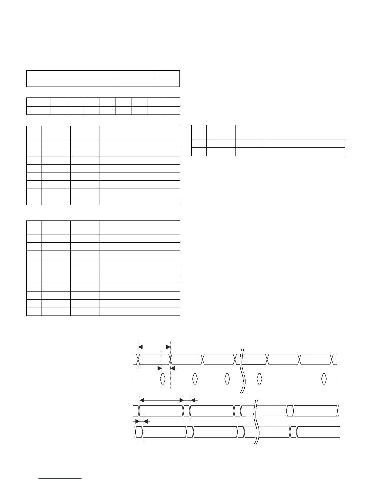
6-2. KEY/DISPLAY SCAN
Key/display scan and key read are performed at the following timing.
1
Key/display scan cycle: 10ms
2
Blanking time: 50us
3
KEY DATA READ timing: Read before 10~100us of strobe signal
OFF.
Key/Display-related Register
<LED Segment Signal> Write
<CPU PORT>
KS3~0 : KEY strobe signal is generated.
LS3~0 : POP UP Display strobe signal is generated.
R0#~KR9# : Flat Keyboard KEY Return signal
KR0#~KR7# : Normal Keyboard KEY Return signal
The mode key switch and other signals are read at CPU ports P142 and
P143 at the key strobe timing.
Reading is made 10~100us before the strobe signal OFF..
The Flat Keyboard takes key data in twice during the strobe period.
For read timing, refer to the timing chart below.
Function Address R/W
LED Segment Signal 100000h W
Address Bit7 Bit6 Bit5 Bit4 Bit3 Bit2 Bit1 Bit0
100000h DP g f e d c B a
No. CPU PORT
Signal to
be used
Function
131 P150 KS0 KEY STROBE SIGNAL 0
129 P151 KS1 KEY STROBE SIGNAL 1
128 P152 KS2 KEY STROBE SIGNAL 2
127 P153 KS3 KEY STROBE SIGNAL 3
126 P154 LS0 LED STROBE SIGNAL 0
125 P155 LS1 LED STROBE SIGNAL 1
124 P156 LS2 LED STROBE SIGNAL 2
123 P157 LS3 LED STROBE SIGNAL 3
No. CPU PORT
Signal to
be used
Function
46 P70 KR0# KEY RETURN SIGNAL 0
45 P71 KR1# KEY RETURN SIGNAL 1
44 P72 KR2# KEY RETURN SIGNAL 2
43 P73 KR3# KEY RETURN SIGNAL 3
42 P74 KR4# KEY RETURN SIGNAL 4
41 P75 KR5# KEY RETURN SIGNAL 5
40 P76 KR6# KEY RETURN SIGNAL 6
39 P77 KR7# KEY RETURN SIGNAL 7
14 P140 KR8# KEY RETURN SIGNAL 8
13 P141 KR9# KEY RETURN SIGNAL 9
No. CPU PORT
Signal to
be used
Function
12 P142 MODE# MODE KEY SIGNAL
11 P143 FSR# FEED SENS SIGNAL
P142 ST0 : MODE Key SRV “0” SRV mode
ST1 : MODE Key PGM “0” PGM mode
ST2 : MODE Key VOID “0” VOID mode
ST3 : MODE Key OP X/Z “0” OP X/Z mode
ST4 : MODE Key REG “0” REG mode
ST5 : MODE Key MGR “0” MGR mode
ST6 : MODE Key X1/Z1 “0” X1/Z1 mode
ST7 : MODE Key X2/Z2 “0” X2/Z2 mode
P143 ST10 : Receipt feed “0” Receipt feed
ST11: Journal feed “0” Journal feed
ST13 : Keypad select “1” Flat key
“1” JNormal key
9h
Fh 0h
Max.10us
0h 1h FhFh
950 25us
10 - 100us
0h 1h 2h Fh 0h
588us ±20us
50 10us
KS0 - 3
LS0 - 3
Key Return Sinnal
(0h~Fh repeat)
(0h~9h repeat)
LED Segment
Signal
BLANK BLANK BLANK
1ST DIGIT
DISPLAY DATA
1ST DIGIT
DISPLAY DATA
2nd DIGIT
DISPLAY DATA