ER-A520/A530 Dealer Knowledge Book
Page 198 of 266 Specifications subject to change without notice: Revision date 10/07
3. Installation Sequence:
1) Remove the AC power cord of the ER-A520 or ER-A530 from the wall outlet.
2) Connect the DB9 Data Tran SL cable to CH-1or CH-2 of the ECR.
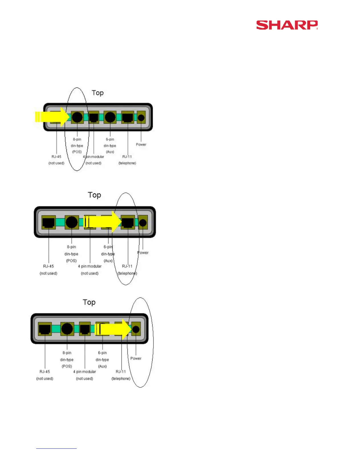
3) Connect the 8 pin DIN to the receptacle marked “ECR/POS” at the Data Tran SL.
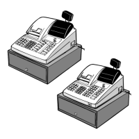
4) Connect the RJ-11 (telephone) jack to the DataTran 162 modem as indicated below.
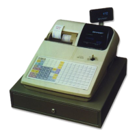
5) Connect the external power adapter to the receptacle of the Data Tran SL.
6) Plug the AC power cord of the ER-A520 and ER-A530 into the wall outlet.
7) Plug the Data Tran SL external power adapter into the wall outlet.
Note: