Ю
ЮрийAug 20, 2025
а если диск не крутится но головка приэтом фокусирует?? что за причина??
а если диск не крутится но головка приэтом фокусирует?? что за причина??
| Type | Stereo System |
|---|---|
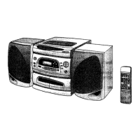
| Brand | Sharp |
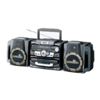
| Model | GX-CD1200W BK |
| Category | Stereo System |
| Color | Black |
| CD Player | Yes |
| Bluetooth | Yes |
| USB Playback | Yes |
| Remote Control | Yes |
| Connectivity | Bluetooth, USB |
| Playable Media | CD, CD-R/RW |
| Radio Tuner | FM |
| Tuner | FM |
Details the power source, power consumption, output power, input/output terminals, dimensions, and weight of the system.
Provides frequency range details for FM, SW1, SW2, and MW radio bands.
Lists frequency response, signal-to-noise ratio, wow and flutter, motor, and bias/erase systems for the tape deck.
Details speaker type, maximum input power, rated input power, impedance, dimensions, and weight.
Illustrates and identifies AC power supply cords and plug adapters for the unit.
Step-by-step instructions for correctly fitting the dial pointer on the tuner mechanism.
Details the step-by-step process for disassembling the main unit, including screw and socket removal.
Outlines the steps required to remove and disassemble the speaker unit components.
Provides instructions on how to remove and reinstall the CD mechanism and its pickup.
Details adjustment points for torque, head azimuth, and tape speed in the mechanism section.
Specifies adjustment points for FM IF/RF and AM IF/RF tuning stages.
Covers adjustments for bias oscillation, beat cancel switch, and amplifier sensitivity.
Explains how to enter and operate the CD section in test mode for diagnostics.
Details the procedure for entering the LCD mode for CD section testing.
Guides on confirming the laser lighting function for the CD pickup.
Provides notes on resistor/capacitor symbols, voltage measurements, and schematic changes.
Lists common transistor and LED types used, with front view diagrams.
Tabulates measured voltages at various IC pins under different operating conditions.
Instructions and cautions for using a CD lens cleaning disc to maintain optical pickup performance.
Diagnostic steps for identifying focus failure, including waveform checks.
Diagnostic steps for spindle motor CLV servo failures, including waveform checks.
Troubleshooting steps for sled motor operation failures, including waveform and voltage checks.
Diagnostic steps for sled servo failures, including waveform checks.
Explains the coding system used for identifying capacitor and resistor types and values.
Lists other electronic components such as connectors, switches, and jacks.
Details parts specific to the CD mechanism, including gears, motors, and covers.
Lists parts related to the unit's chassis, panels, knobs, and internal supports.
Lists components for the speaker enclosure, including baffles, screws, and speaker units.
Details included accessories, packing materials, and labels.
Lists main PWB assemblies and other service-specific parts.