– 42 –
HT-CN400DVH/HT-CN400DVE/HT-CN500DVH/HT-CN500DVE
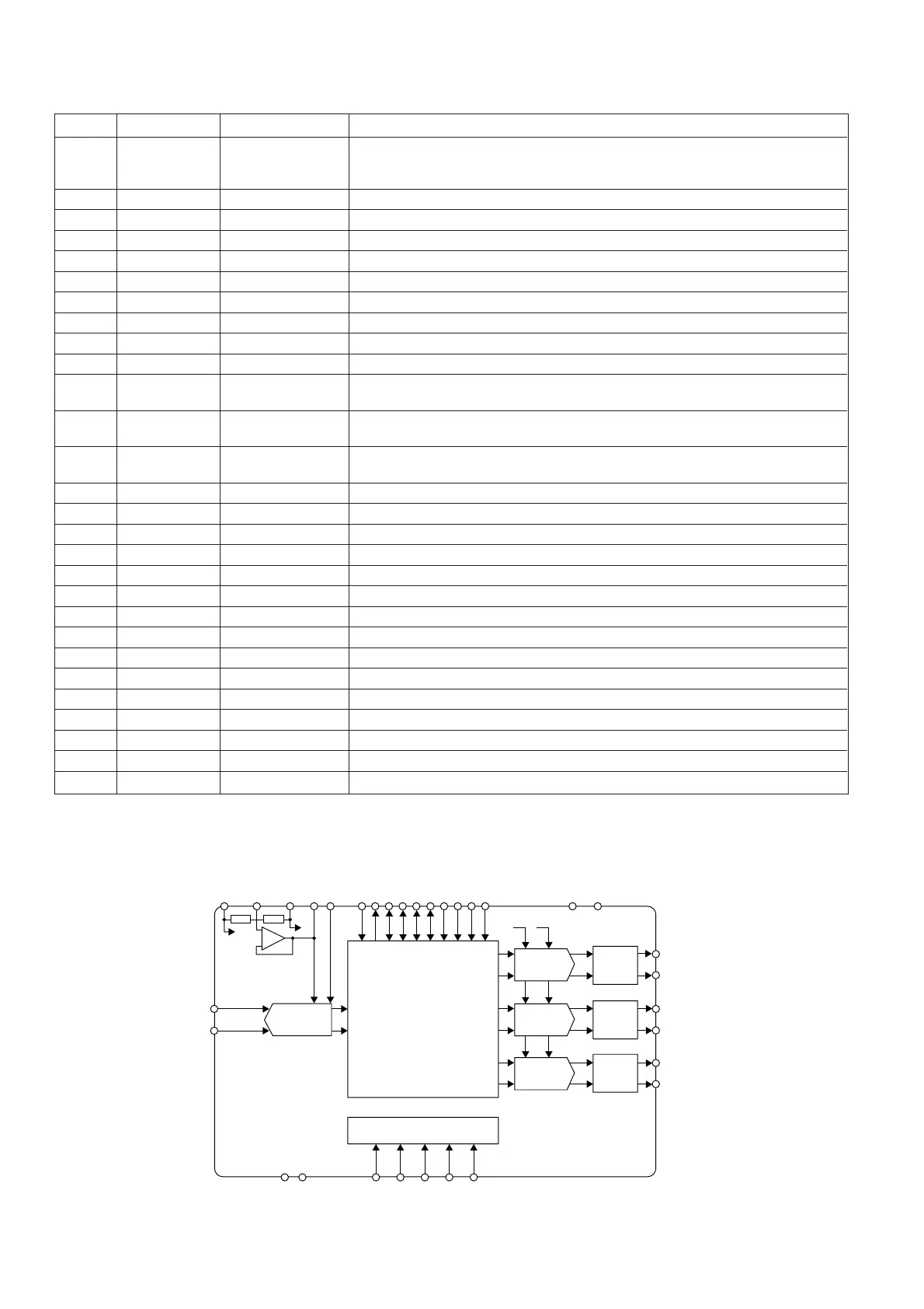
IC110 92LRCI8772-001: 6CH D/A 2CH A/D (WM8772)
1 MODE Digital input Control format selection.
0= Software control.
1= Hardware control.
2 MCK Digital input Master clock; 256, 384, 512 or 768 fs (fs= word clock frequency).
3 BCLK Digital input/output Audio interface bit clock.
4 LRC Digital input/output Audio left/right word clock.
5 DVDD Supply Digital positive supply.
6 DGND Supply Digital negative supply.
7 DIN1 Digital input DAC channel 1 data input.
8 DIN2 Digital input DAC channel 2 data input.
9 DIN3 Digital input DAC channel 3 data input.
10 DOUT Digital output ADC data output.
11 ML/I2S Digital input Software Mode: Serial interface Latch signal.
Hardware Mode: Input Audio Data Format.
12 MC/IWL Digital input Software Mode: Serial control interface clock.
Hardware Mode: Audio data input word length.
13 MD/DM Digital input Software Mode: Serial interface data.
Hardware Mode: De-emphasis selection.
14* MUTE Digital input/output DAC Zero Flag output or DAC mute input.
15 REFADC Analogue output ADC reference buffer decoupling pin; 10 µF external decoupling.
16 VREFN Supply ADC and DAC negative supply and substrate connection.
17 VREFP Supply DAC positive reference supply.
18 VMID Analogue output Midrail divider decoupling pin; 10 µF external decoupling.
19 AINR Analogue input ADC right input.
20 AINL Analogue input ADC left input.
21 VOUT1L Analogue output DAC channel 1 left output.
22 VOUT1R Analogue output DAC channel 1 right output.
23 VOUT2L Analogue output DAC channel 2 left output.
24 VOUT2R Analogue output DAC channel 2 right output.
25 VOUT3L Analogue output DAC channel 3 left output.
26 VOUT3R Analogue output DAC channel 3 right output.
27 AGND Supply Analogue negative supply and substrate connection.
28 AVDD Supply Analogue positive supply.
Port NamePin No. Input/Output
Function
Note: Digital input pins have Schmitt trigger input buffers.
In this unit, the terminal with asterisk mark (*) is (open) terminal which is not connected to the outside.
DACVREFN
VMID
DVDD
DGND
MUTE
MODE
ML/I2S
MC/IWL
MD/DM
DACVREFP
REFADC
ADCVREFN
ADCMCLK
DOUT
ADCLRC
DACLRC
ADCBCLK
AACBCLK
DIN1
DIN2
DIN3
DACMCLK
AVDD
AGND
VOUT1L
VOUT1R
VOUT2L
VOUT2R
VOUT3L
VOUT3R
STEREO
ADC
STEREO
DAC
LOW
PASS
FILTER
LOW
PASS
FILTER
LOW
PASS
FILTER
STEREO
DAC
STEREO
DAC
VREFN VREFP
AUDIO
INTERFACE
&
DIGITAL
FILTERS
CONTROL INTERFACE
AINL
AINR
+
–
Figure 42 BLOCK DIAGRAM OF IC