HT-DV30H
6 – 1
AudioCD-DV650WService ManualCD-DV650WMarketE
CHAPTER 6. CIRCUIT SCHEMATICS AND PARTS LAYOUT
[1] Notes On Schematic Diagram
• Resistor:
To differentiate the units of resistors, such symbol as K
and M are used: the symbol K means 1000 ohm and the
symbol M means 1000 kohm and the resistor without any
symbol is ohm-type resistor. Besides, the one with “Fus-
ible” is a fuse type.
• Capacitor:
To indicate the unit of capacitor, a symbol P is used: this
symbol P means pico-farad and the unit of the capacitor
without such a symbol is microfarad. As to electrolytic
capacitor, the expression “capacitance/withstand voltage”
is used.
(CH), (TH), (RH), (UJ): Temperature compensation
(ML): Mylar type
(P.P.): Polypropylene type
• Schematic diagram and Wiring Side of P.W.Board for this
model are subject to change for improvement without
prior notice.
• The indicated voltage in each section is the one measured
by Digital Multimeter between such a section and the
chassis with no signal given.
1. In the tuner section,
indicates FM stereo
2. In the main section, DVD is being played back.
3. In the power section, DVD is being played back.
4. In the DVD section, the DVD is stopped.
• Parts marked with “ “ ( ) are important
for maintaining the safety of the set. Be sure to replace
these parts with specified ones for maintaining the safety
and performance of the set.
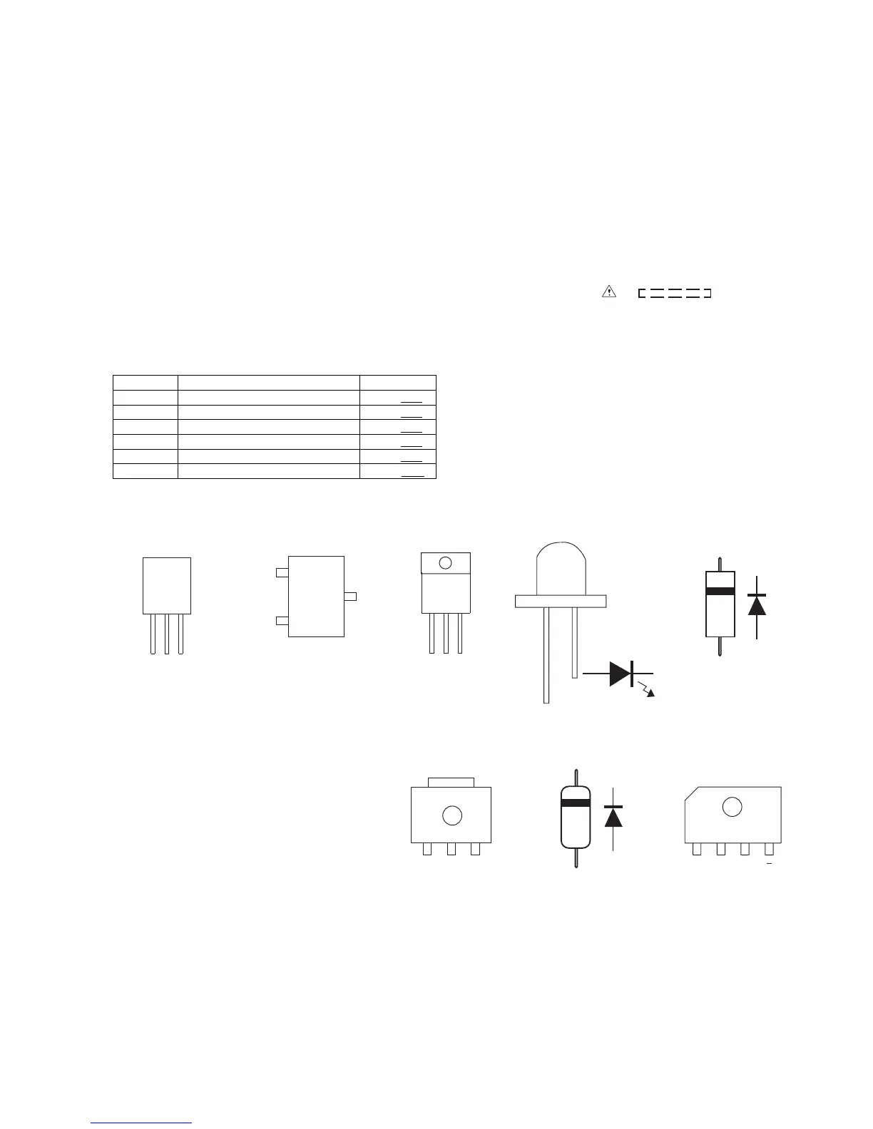
[2] Types Of Transistor And LED
REF. NO DESCRIPTION POSITION
SW501 POWER ON/STANDBY ON—OFF
SW507 DVD/CD/USB PLAY/PAUSE ON—OFF
SW508 DISC/USB STOP ON—OFF
SW509 FUNCTION ON—OFF
SW510 DISC OPEN/CLOSE ON—OFF
VR501 VOLUME MIN—MAX
KRA107 S
KRC102 S
KRC104 S
KRC107 S
KTA1504 GR
KTC3875 GR
KTK5133 S
KTC2875 B
SK536
KTA1298 Y
SC3928 AR
B
(3)
E
(1)
C
(2)
TOP
VIEW
KIA78L05
KTA1023 Y
KIA431 A
KTA1273Y
VIEW
FRONT
E C B
VIEW
FRONT
1 2 3
(S)(G)(D)
(1)(2)(3)
KIA7809
KIA7812
STTH1002CFP
06N80C3
2SA2012
KTC4375Y
FRONT
VIEW
304VT2H
503BC2E
HSS4148
1N4004
FH3+++
MA111
BCE
TOP VIEW
D10XB60F
+ AC AC
FRONT VIEW