1. REMOVAL OF MECHANICAL PARTS
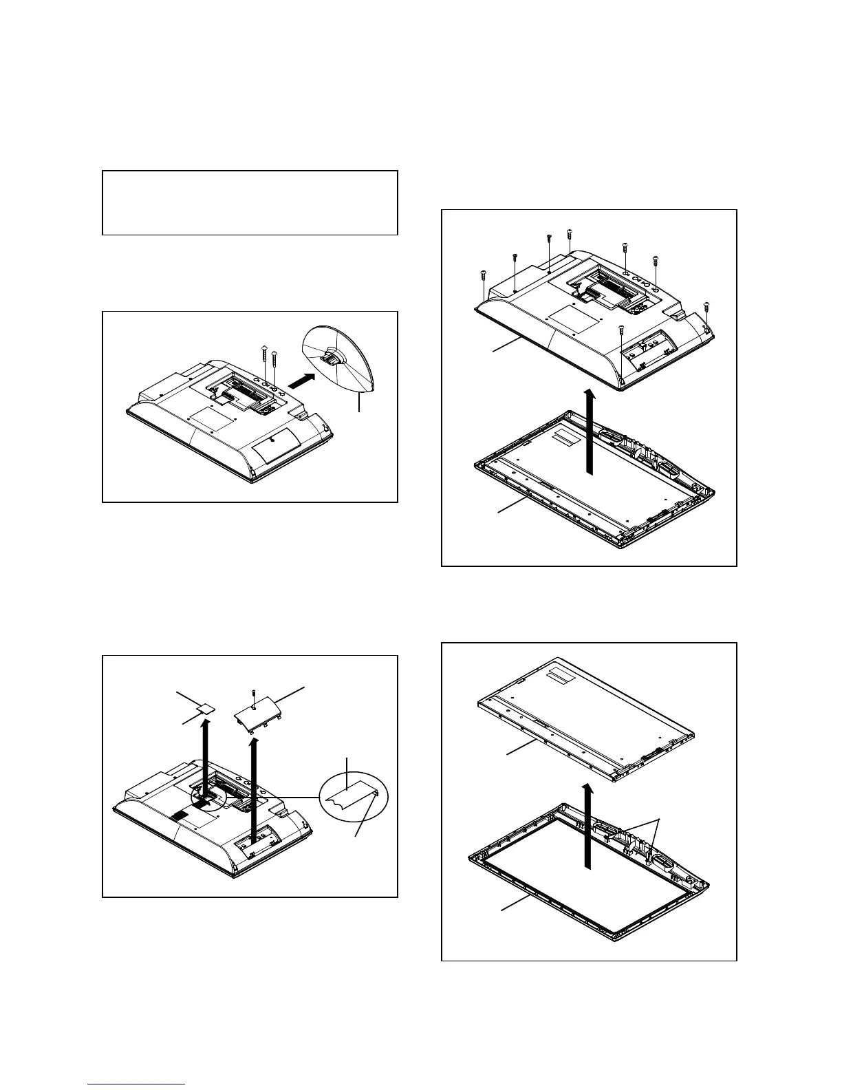
1-3: BACK CABINET ASS'Y (Refer to Fig. 1-3)
AND P.C. BOARDS
CAUTION
3. Remove the Back Cabinet Ass'y in the direction of arrow.
Be careful not to remove the FFC cable forcibly, because
the FFC cable may be damaged.
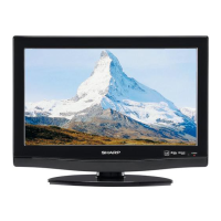
1-1: STAND ASS'Y (Refer to Fig. 1-1)
Remove the Stand Ass'y in the direction of arrow.
Stand Ass'y
(1)
(2)
(1)
(2)
(2)
(2)
(2)
(2)
Back Cabinet Ass'y
B1-1
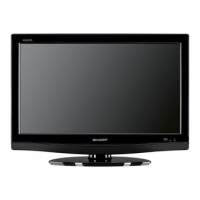
1-2: COVER INVERTER and COVER CONNECTOR
1. Remove the screw (1).
2. Remove the Cover Inverter in the direction of arrow (A).
3. Disconnect the following connectors:
1-4: LCD PANEL (Refer to Fig. 1-4)
(CP7001, CP7002, CP7003 and CP7004).
4. Unlock the support (2). 1. Unlock the 2 supports (1).
Remove the Cover Connector in the direction of arrow (B).
Remove the LCD PANEL in the direction of arrow.
Disconnect the following connector:
(1)
Cover Inverter
Fig. 1-2
Fig. 1-4
Fig. 1-3
Cover Connector
FFC Cable
Connector
(A)
(B)
Front Cabinet
Front Cabinet Ass'y
LCD Panel
(2)
(1)
B1-1