108
LC-32/37GD8E/RU
LC-32/37BT8E/RU
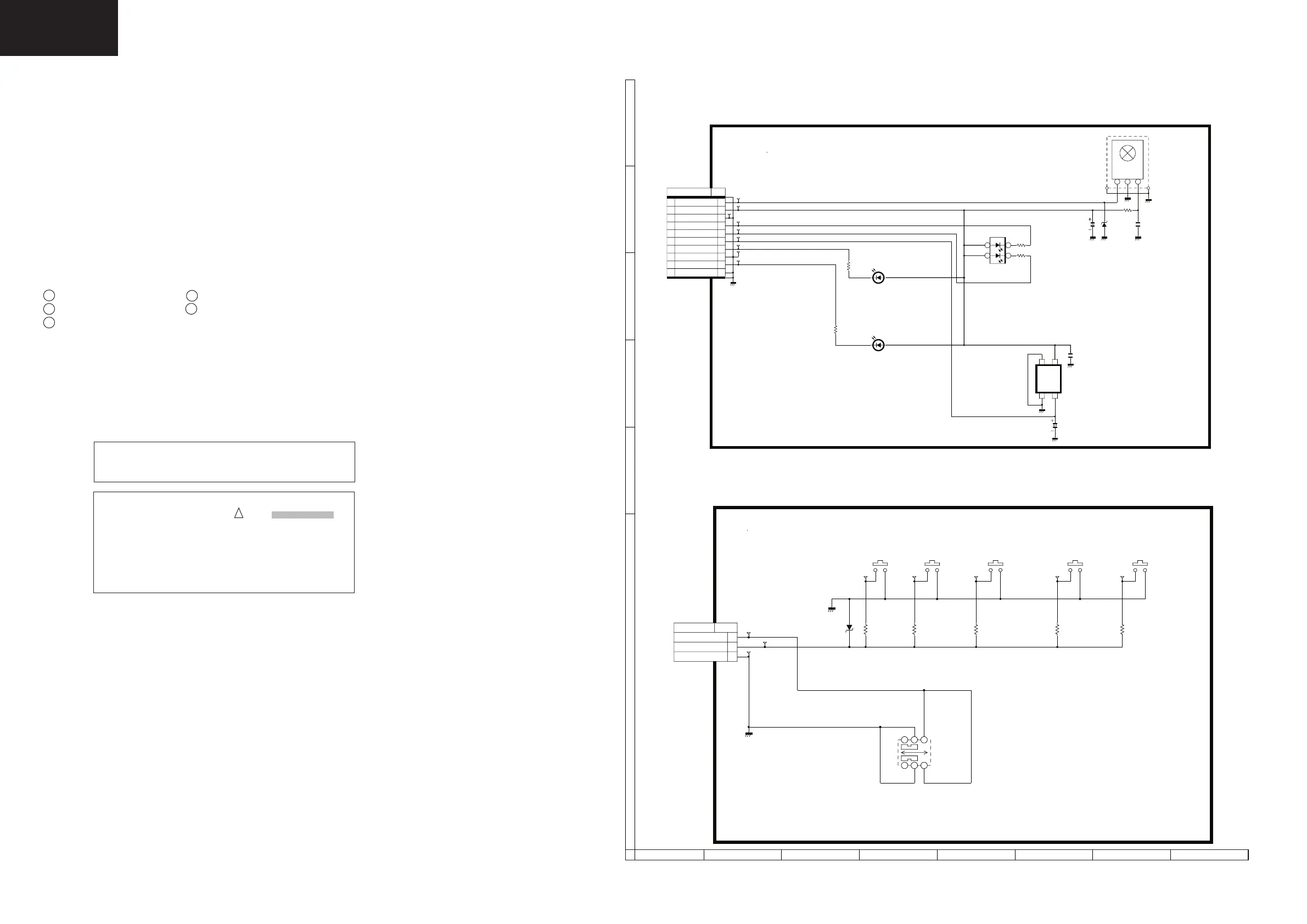
LC-32/37GD8, LC-32/37BT8 RC/LED Unit Diagram
LC-32/37GD8, LC-32/37BT8 KEY Unit Diagram
IMPORTANT SAFETY NOTICE:
PARTS MARKED WITH “ ” ( )
ARE
IMPORTANT FOR MAINTAINING THE SAFETY OF
THE SET. BE SURE TO REPLACE THESE PARTS
WITH SPECIFIED ONES FOR MAINTAINING THE
SAFETY AND PERFORMANCE OF THE SET.
SCHEMATIC DIAGRAMS
Description:
VOLTAGE MEASUREMENT CONDITION:
1. The voltages at test points are measured on exclusive AC adaptor and the stable supply voltage of AC 230V.
Signals are fed by a color bar signal generator for servicing purpose and the above voltages are measured with a
20k ohm/V tester.
INDICATION OF RESISTOR & CAPACITOR:
RESISTOR
1. The unit of resistance “
Ω ” is omitted. (K=kΩ=1000 Ω, M=MΩ).
2. All resistors are ± 5%, unless otherwise noted. (J= ± 5%, F= ± 1%, D= ± 0.5%)
3. All resistors are 1/16W, unless otherwise noted.
4. All resistors are Carbon type, unless otherwise noted.
C : Solid W : Cement
S : Oxide Film T : Special
N : Metal Coating
CAPACITOR
1. All capacitors are µF, unless otherwise noted. (P=pF=µµ F).
2. All capacitors are 50V, unless otherwise noted.
3. All capacitors are Ceramic type, unless otherwise noted.
(ML): Mylar (TA): Tantalum
(PF): Polypro Film (ST): Styrol
CAUTION:
This circuit diagram is original one, therefore there may be a
slight difference from yours.
!
I
H
G
F
E
D
C
B
1
2 3 4 5
6
7 8
A