EasyManua.ls Logo

Sharp LC-32R24B

Sharp LC-32R24B
108 pages
To Next Page IconTo Next Page
Loading...
SERVICE MANUAL
Parts marked with " " are important for maintaining the safety of the set. Be sure to replace these parts with specified ones for maintaining the
safety and performance of the set.
This document has been published to be used for
after sales service only.
The contents are subject to change without notice.
SAFETY PRECAUTION
IMPORTANT SERVICE SAFETY PRE-
CAUTION ............................................................i
PRECAUTIONS FOR USING LEAD-FREE
SOLDER ...........................................................ii
PRECAUTIONS IN SERVICING THE
HDCP-KEY ROM ...............................................ii
CHAPTER 1. OPERATION MANUAL
[1] SPECIFICATIONS ........................................ 1-1
[2] OPERATION MANUAL .................................. 1-2
[3] DIMENSIONS ............................................... 1-7
CHAPTER 2. REMOVING OF MAJOR PARTS
[1] REMOVING OF MAJOR PARTS ................... 2-1
CHAPTER 3. ADJUSTMENT
[1] ADJUSTMENT PROCEDURE ....................... 3-1
CHAPTER 4. TROUBLESHOOTING TABLE
[1] TROUBLESHOOTING TABLE....................... 4-1
CHAPTER 5. MAJOR IC INFORMATIONS
[1] MAJOR IC INFORMATIONS .........................5-1
CHAPTER 6. OVERALL WIRING/BLOCK DIAGRAM
[1] OVERALL WIRING DIAGRAM......................6-1
[2] SYSTEM BLOCK DIAGRAM.........................6-2
CHAPTER 7. PRINTED WIRING BOARD ASSEM-
BLIES
[1] MAIN Unit ......................................................7-1
[2] KEY Unit ........................................................7-5
[3] R/C, LED Unit ................................................7-6
CHAPTER 8. SCHEMATIC DIAGRAM
[1] DESCRIPTION OF SCHEMATIC DIA-
GRAM............................................................8-1
[2] SCHEMATIC DIAGRAM................................8-2
Parts Guide
CONTENTS
LC-32R24B
In the interests of user-safety (Required by safety regulations in some countries) the set should be restored to its orig-
inal condition and only parts identical to those specified should be used.
No. S98P4LC32R24B
LCD COLOR TELEVISION
MODEL
LC-32R24B
Question and Answer IconNeed help?

Do you have a question about the Sharp LC-32R24B and is the answer not in the manual?

Sharp LC-32R24B Specifications

General IconGeneral
Screen Size32 inches
Display TypeLCD
USB Ports1
Aspect Ratio16:9
Resolution1366 x 768
Weight8.8 kg
Input PortsComponent, Composite, VGA
Sound Output10 W x 2

Summary

SAFETY PRECAUTION

IMPORTANT SERVICE SAFETY PRECAUTION

Essential safety precautions for service personnel.

PRECAUTIONS FOR USING LEAD-FREE SOLDER

Guidelines for handling lead-free solder during repairs.

PRECAUTIONS IN SERVICING THE HDCP-KEY ROM

Measures for protecting HDCP-KEY ROM information during service.

CHAPTER 1. OPERATION MANUAL

[1] SPECIFICATIONS

Technical specifications of the LCD color television.

[2] OPERATION MANUAL

Instructions for operating the television.

[3] DIMENSIONS

Physical dimensions of the television unit.

CHAPTER 2. REMOVING OF MAJOR PARTS

[1] REMOVING OF MAJOR PARTS

Step-by-step guide for disassembling major components.

CHAPTER 3. ADJUSTMENT

[1] ADJUSTMENT PROCEDURE

Procedures for adjusting the television's settings.

CHAPTER 4. TROUBLESHOOTING TABLE

[1] TROUBLESHOOTING TABLE

A table listing common problems and their solutions.

CHAPTER 5. MAJOR IC INFORMATIONS

[1] MAJOR IC INFORMATIONS

Information on the key integrated circuits used in the unit.

CHAPTER 6. OVERALL WIRINGBLOCK DIAGRAM

[1] OVERALL WIRING DIAGRAM

A comprehensive wiring diagram of the television's internal connections.

[2] SYSTEM BLOCK DIAGRAM

Block diagram illustrating the system's functional units and their interconnections.

CHAPTER 7. PRINTED WIRING BOARD ASSEMBLIES

[1] MAIN Unit

Printed wiring board layout for the main unit.

[2] KEY Unit

Printed wiring board layout for the key unit.

[3] RC, LED Unit

Printed wiring board layout for the R/C and LED unit.

CHAPTER 8. SCHEMATIC DIAGRAM

[1] DESCRIPTION OF SCHEMATIC DIAGRAM

Explanation of symbols and conventions used in schematic diagrams.

[2] SCHEMATIC DIAGRAM

Detailed schematic diagrams of the television's circuitry.

SAFETY PRECAUTION

CAUTION: FUSE REPLACEMENT FOR FIRE PROTECTION

Warning about using correct fuse types for fire prevention.

SAFETY NOTICE ON PART REPLACEMENT

Information on safety-related characteristics of parts and replacements.

PRECAUTIONS FOR USING LEAD-FREE SOLDER

PRECAUTIONS IN SERVICING THE HDCP-KEY ROM

CHAPTER 1. OPERATION MANUAL

[1] SPECIFICATIONS

Technical specifications of the LCD color television.

CHAPTER 1. OPERATION MANUAL

[2] OPERATION MANUAL

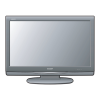
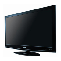
Part names and identification for the TV's external components.

CHAPTER 1. OPERATION MANUAL

Remote Control Unit

Identification and function of remote control buttons.

QUICK REFERENCE

AttachingDetaching the Stand

Instructions for attaching and detaching the TV stand.

Setting the TV on the Wall

Guidelines and precautions for wall-mounting the television.

CHAPTER 4. TROUBLESHOOTING TABLE

Troubleshooting

A guide to diagnose and resolve common operational issues.

Cautions regarding use in high and low temperature environments

PC Compatibility Chart

CHAPTER 1. OPERATION MANUAL

[3] DIMENSIONS

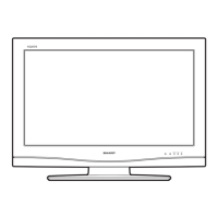
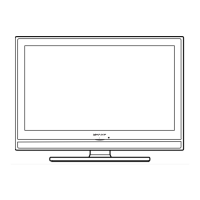
Detailed physical dimensions of the television unit in millimeters.

CHAPTER 2. REMOVING OF MAJOR PARTS

[1] REMOVING OF MAJOR PARTS

Visual guide for removing the stand and rear cabinet.

CHAPTER 2. REMOVING OF MAJOR PARTS

CHAPTER 2. REMOVING OF MAJOR PARTS

Remove the Speaker (L) (R). Remove the 3 lock screws and detach the POWERINVERTER Unit.

Instructions for removing speakers and the power/inverter unit.

CHAPTER 2. REMOVING OF MAJOR PARTS

CHAPTER 3. ADJUSTMENT

1. After replacement of any PWB unit andor IC for repair, please note the following.

Notes on replacing PWB units or ICs, including software updates.

2.1. Software version upgrade

Overview of software versions and upgrade methods.

2.2. Main software version upgrade

Steps for preparing and performing the main software upgrade.

CHAPTER 3. ADJUSTMENT

6. Upon completion of the whole process, the upgrade success screen as shown below appears.

Confirmation of successful software upgrade and version check.

CHAPTER 3. ADJUSTMENT

2.3. Monitor microprocessor software version upgrade

Procedures for upgrading the monitor microprocessor software.

CHAPTER 3. ADJUSTMENT

2.4. Upgrading Panel timing controller software

Steps to upgrade the panel timing controller software.

CHAPTER 3. ADJUSTMENT

3. Entering and exiting the adjustment process mode

How to enter and exit the service adjustment mode.

4. Remote controller key operation and description of display in adjustment process mode

Key operations and display descriptions for the adjustment mode.

CHAPTER 3. ADJUSTMENT

5. List of adjustment process mode menu

Detailed list of available adjustment items and their descriptions.

1) Green power LED

LED flashing timing chart for error notification.

Explains LED flashing patterns for error notifications.

2) Power failure details (Power LED flashes twice and OPC LED flashes)

3) Communication failure details (Power LED flashes 3 times and OPC LED flash)

PARTS GUIDE

[1] PRINTED WIRING BOARD ASSEMBLIES

List of printed wiring board assemblies.

[5] DUNTKE450 FM09 (MAIN Unit)

Parts list for the MAIN Unit.

[7] CABINET AND MECHANICAL PARTS

List of cabinet and mechanical parts.

[10] PACKING PARTS (NOT REPLACEMENT ITEM)

List of packing parts not for replacement.

[6] NOTE (Conductive cloth tapeGasket)

Attention

Important attention regarding the use of new conductive cloth tape/gasket.

[7] CABINET AND MECHANICAL PARTS

Front Cabinet Assy

Assembly details for the front cabinet.

Rear Cabinet Assy

Assembly details for the rear cabinet.

Stand Unit

Details of the stand unit.

[8] LCD MODULE Assembly

LCD MODULE Assembly

Exploded view of the LCD module assembly components.

[8] LCD MODULE Assembly

LCD Module Assy

List of parts for the LCD Module Assembly.

Lamp Unit, x10

Parts list for lamp units.

[9] SUPPLIED ACCESSORIES

Cable Clamp

Accessory: Cable Clamp.

AC Cord

Accessory: AC Cord.

Remote Control Unit

Accessory: Remote Control Unit.

[10] PACKING PARTS (NOT REPLACEMENT ITEM)

Packing Case

Packing part: Packing Case.

[11] SERVICE JIG (USE FOR SERVICING)

Connecting Cord (80 pin FFC L=1000 mm) x2, MAIN to L

Service jig: Connecting cord for MAIN to L.

Related product manuals