EasyManua.ls Logo

Sharp LC-32WD1E/S/RU User Manual

Sharp LC-32WD1E/S/RU
202 pages
To Next Page IconTo Next Page
Page #1 background imageLoading...
Page #1 background image
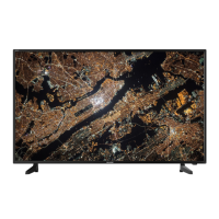
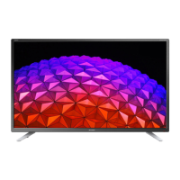
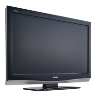
LC-32WD1E/S/RU, LC-37WD1E/S/RU, LC-42WD1E/S/RU, and LC-32/37/42WT1E
LCD COLOUR TELEVISION
LC-32WD1E/S/RU
LC-37WD1E/S/RU
LC-42WD1E/S/RU
LC-32WT1E
LC-37WT1E
MODELS LC-42WT1E
SERVICE MANUAL
SHPRN000222C-GLDN
This document has been published to be used for
after sales service only.
The contents are subject to change without notice.
No. S57J1LC32WD1E
In the interests of user-safety (required by safety regulations in some countries) the set should be restored to its original
condition and only parts identical to those specified should be used.
CONTENTS
Parts marked with " " are important for maintaining the safety of the set. Be sure to replace these parts with specified ones for maintaining the
safety and performance of the set.
PREFACE AND SAFETY INFORMATION
[1] PRINTING FROM THIS BOOK . . . . . . . . . . . . . . . . . . .i
[2] SAFETY AND EMI PRECAUTIONS . . . . . . . . . . . . . . ii
[3] PRECAUTIONS FOR LEAD-FREE SOLDER. . . . . . .iii
[4] SAFETY WARNINGS . . . . . . . . . . . . . . . . . . . . . . . . .iii
CHAPTER 1 SPECIFICATIONS
[1] SPECIFICATIONS . . . . . . . . . . . . . . . . . . . . . . . . . 1-1
CHAPTER 2 OPERATION MANUAL
[1] OPERATION MANUAL . . . . . . . . . . . . . . . . . . . . . . 2-1
CHAPTER 3 DIMENSIONS
[1] DIMENSIONS . . . . . . . . . . . . . . . . . . . . . . . . . . . . . 3-1
CHAPTER 4 REMOVING OF MAJOR PARTS
[1] REMOVE MAJOR PARTS
LC-32WD1E/S/RU AND LC-32WT1E . . . . . . . . . . . 4-1
[2] REMOVE MAJOR PARTS
LC-37WD1E/S/RU AND LC-37WT1E . . . . . . . . . . . 4-4
[3] REMOVE MAJOR PARTS
LC-42WD1E/S/RU AND LC-42WT1E . . . . . . . . . . . 4-7
CHAPTER 5 ADJUSTMENT PROCEDURES
[1] UPGRADING SOFTWARE . . . . . . . . . . . . . . . . . . . 5-1
[2] TROUBLESHOOTING SOFTWARE UPGRADE . . 5-7
[3] ENTERING THE PUBLIC MODE MENUS . . . . . . . 5-8
[4] REMOTE CONTROL KEY OPERATION
IN PUBLIC MODE. . . . . . . . . . . . . . . . . . . . . . . . . . 5-8
[5] PUBLIC MODE SETTINGS. . . . . . . . . . . . . . . . . . . 5-8
[6] ENTERING THE SERVICE MENUS. . . . . . . . . . . . 5-8
[7] SERVICE MODE REMOTE CONTROL KEY
AND DESCRIPTION OF DISPLAY. . . . . . . . . . . . . 5-9
[8] SERVICE MENU SETTINGS . . . . . . . . . . . . . . . . . 5-9
CHAPTER 6 TROUBLESHOOTING TABLE
CHAPTER 7 MAJOR IC INFORMATION
[1] MAJOR IC INFORMATION . . . . . . . . . . . . . . . . . . . 7-1
CHAPTER 8 OVERALL WIRING DIAGRAM
[1] OVERALL WIRING DIAGRAM
(LC-32WD1E/S/RU, LC-32WT1E) . . . . . . . . . . . . . . 8-1
[2] OVERALL WIRING DIAGRAM
(LC-37WD1E/S/RU, LC-37WT1E) . . . . . . . . . . . . . . 8-2
[3] OVERALL WIRING DIAGRAM
(LC-42WD1E/S/RU, LC-42WT1E) . . . . . . . . . . . . . . 8-3
[4] BLOCK DIAGRAMS. . . . . . . . . . . . . . . . . . . . . . . . . 8-4
CHAPTER 9 PRINTED WIRING BOARD
[1] LED/IR . . . . . . . . . . . . . . . . . . . . . . . . . . . . . . . . . . . 9-1
[2] SIDE I/O . . . . . . . . . . . . . . . . . . . . . . . . . . . . . . . . . . 9-2
[3] KEYPAD. . . . . . . . . . . . . . . . . . . . . . . . . . . . . . . . . . 9-3
[4] POWER UNIT PRINTED WIRING BOARD
(LC-32WD1E/S/RU, LC-37WD1E/S/RU,
LC-42WD1E/S/RU, LC-32/37/42WT1E). . . . . . . . . . 9-4
[5] MAINBOARD . . . . . . . . . . . . . . . . . . . . . . . . . . . . . . 9-5
CHAPTER 10 SCHEMATIC DIAGRAM
[1] DESCRIPTION OF SCHEMATIC DIAGRAM. . . . . 10-1
[1] LED/IR . . . . . . . . . . . . . . . . . . . . . . . . . . . . . . . . . . 10-2
[2] SIDE I/O . . . . . . . . . . . . . . . . . . . . . . . . . . . . . . . . . 10-3
[3] KEYBOARD . . . . . . . . . . . . . . . . . . . . . . . . . . . . . . 10-4
[4] MAINBOARD . . . . . . . . . . . . . . . . . . . . . . . . . . . . . 10-5
[5] POWER SUPPLY UNIT (LC-32WD1E/S/RU,
LC-37WD1E/S/RU, AND LC-32/37WT1E). . . . . . 10-19
[6] POWER SUPPLY UNIT (LC-42WD1E/S/RU,
LC-42WT1E) . . . . . . . . . . . . . . . . . . . . . . . . . . . . 10-20
PARTS GUIDE
Question and Answer IconNeed help?

Do you have a question about the Sharp LC-32WD1E/S/RU and is the answer not in the manual?

Sharp LC-32WD1E/S/RU Specifications

General IconGeneral
Screen Size32 inches
Display TypeLCD
HDMI Ports2
USB Ports1
HD TechnologyHD Ready
Display TechnologyLCD
Refresh Rate50 Hz
Built-in Wi-FiNo
Smart TVNo
Resolution1366 x 768
Weight8.3 kg
TunerAnalog and Digital

Summary

Preface and Safety Information

Safety and EMI Precautions

Important service safety precautions and EMI considerations for technicians.

Precautions for Lead-Free Solder

Guidelines and precautions for using lead-free solder during repair.

Safety Warnings

Essential safety warnings for service personnel and power safety.

Chapter 1 Specifications

Specifications

Detailed technical specifications for the LCD color television models.

Chapter 2 Operation Manual

Operation Manual

Information on television operation, including rear and front views and remote control functions.

Chapter 3 Dimensions

Dimensions

Physical dimensions and measurements for the different TV models.

Chapter 4 Removing of Major Parts

Remove Major Parts LC-32WD1E/S/RU and LC-32WT1E

Step-by-step instructions for disassembling major components of the LC-32WD1E/S/RU and LC-32WT1E models.

Remove Major Parts LC-37WD1E/S/RU and LC-37WT1E

Step-by-step instructions for disassembling major components of the LC-37WD1E/S/RU and LC-37WT1E models.

Remove Major Parts LC-42WD1E/S/RU and LC-42WT1E

Step-by-step instructions for disassembling major components of the LC-42WD1E/S/RU and LC-42WT1E models.

Chapter 5 Adjustment Procedures

Software Upgrade and Troubleshooting

Procedures for upgrading TV software, including file types, time, and troubleshooting steps.

Public Mode Operations

Instructions for entering public mode, remote control key operations, and public mode settings.

Service Menu and Calibration

Guidance on entering service menus, using calibration items, and adjusting service settings.

Chapter 6 Troubleshooting Table

Chapter 7 Major IC Information

Major IC Information

Detailed information on major integrated circuits used in the television, including part codes and descriptions.

Chapter 8 Overall Wiring and Block Diagrams

Overall Wiring Diagrams

Wiring diagrams illustrating connections between major components for different model series.

Block Diagrams

Functional block diagrams showing the signal flow for video, audio, control, memories, and power units.

Chapter 9 Printed Wiring Boards

Component PWB Diagrams

Printed wiring board layouts for smaller components like LED/IR, Side I/O, and Keypad.

Major Board PWB Diagrams

Printed wiring board layouts for the Power Unit and Mainboard.

Chapter 10 Schematic Diagrams

Schematic Diagram Description

Explanation of component value notation and important safety warnings for schematic diagrams.

Component Schematics

Schematic diagrams for individual components like LED/IR, Side I/O, and Keypad.

Mainboard Schematics

Schematic diagrams detailing the Mainboard, including UOC, Audio AMP, Hirate, PNX, Memories, and CPLD.

Power Supply Schematics

Schematic diagrams for the Power Supply Unit, covering different model series.

SHARP Parts Guide

Printed Wiring Board Assemblies

Part numbers and descriptions for all printed wiring board assemblies.

Power Units

Part numbers and descriptions for the Power Unit components for different models.

Cabinet Parts

Part numbers and descriptions for all cabinet parts, tapes, felts, and miscellaneous items.

Accessories and Packing Parts

List of supplied accessories and packing materials for various models.

Service Jigs

Part numbers and descriptions for service jigs, including software upgrade kits and extension cables.

Related product manuals