LC-37XD1E/RU
3 – 10
6. Special features
* ERROR STANDBY CAUSE (Page 1/13)
The total time when the unit enters the standby due to operational error and cause of error are recorded on EEPROM as much as possible.
The values can be used to locate the fault for repair.
* EEP CLEAR (Page10/13)
Clear of process adjustment EEP value.
7. Inch Setting
8. Video signal adjustment procedure * The adjustment process mode menu is listed in Section 5.
1. Signal check
Signal generator level adjustment check (Adjustment to the specified level)
• Composite signal PAL : 0.7Vp-p ± 0.02Vp-p (Pedestal to white level)
• 15K component signal : Y level 0.7Vp-p ± 0.02Vp-p (Pedestal to white level)
(50 Hz) PB, PR level 0.7Vp-p ± 0.02Vp-p
2. Entering the adjustment process mode
Enter the adjustment process mode according to Section 3.
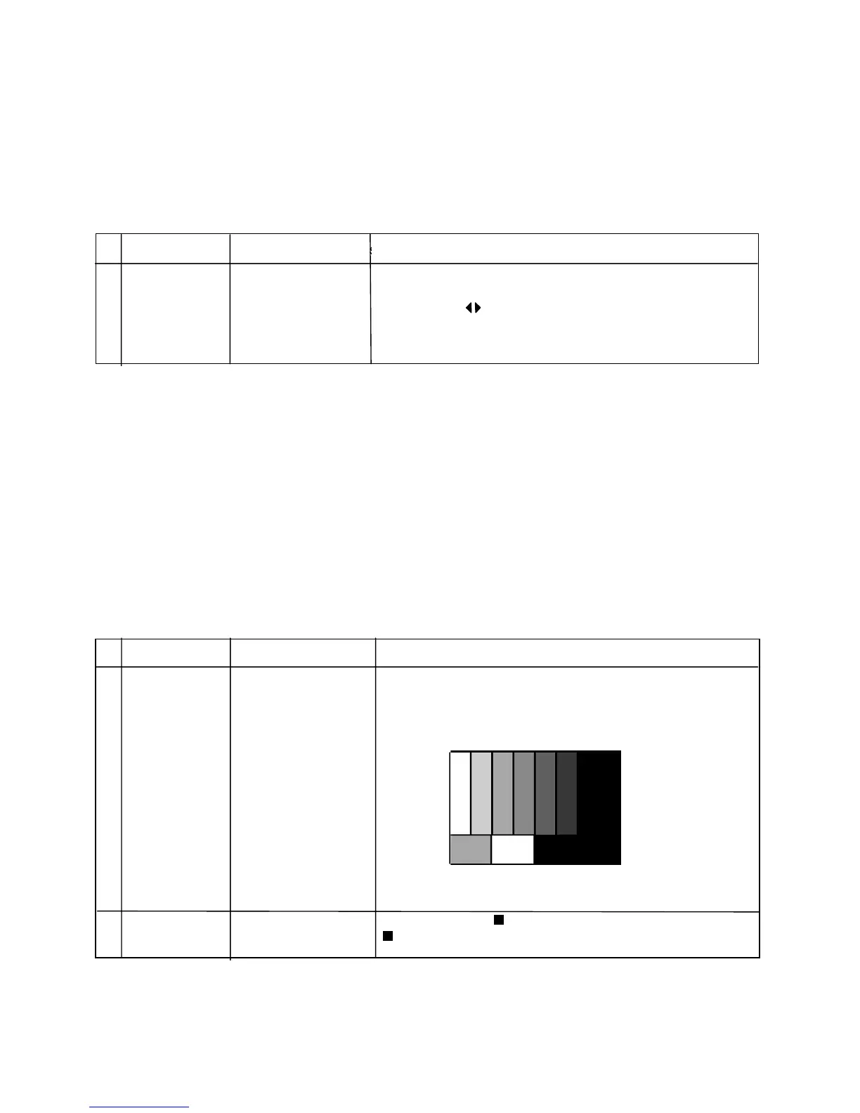
3. RF AGC adjustment 1
1 Factory settings
䊶 Enter the ad
rit Field Colour Bar
RF signal UV [E-12CH]
[Terminal]
TUNER
㸡100% white
2
Auto adjustment Adjustment process Bring the cursor on [ RF AGC BG ADJ] and press [OK]
performance
[PAL+TUNERMAIN] menu
[ RF AGC BG ADJ 㵘OK] appears when finished.
Adjustment Conditions Adjustment㵘procedure
Adjustment poin
t