Parts marked with " " are important for maintaining the safety of the set. Be sure to replace these parts with specified ones for maintaining the
safety and performance of the set.
SERVICE MANUAL
This document has been published to be used for
after sales service only.
The contents are subject to change without notice.
SAFETY PRECAUTION
IMPORTANT SERVICE SAFETY
PRECAUTION.....................................................i
Precautions for using lead-free solder ...............ii
End of life disposal ............................................ iii
OUTLINE
MAJOR SERVICE PARTS ................................iv
CHAPTER 1. SPECIFICATIONS
[1] SPECIFICATIONS ......................................... 1-1
CHAPTER 2. OPERATION MANUAL
[1] Parts Name .................................................... 2-1
[2] OPERATION MANUAL .................................. 2-5
CHAPTER 3. DIMENSIONS
[1] DIMENSIONS
(LC-40LE830E, RU/831E, S) ......................... 3-1
[2] DIMENSIONS
(LC-46LE830E, RU/831E, S) ......................... 3-2
CHAPTER 4. REMOVING OF MAJOR PARTS
[1] REMOVING OF MAJOR PARTS
(LC-40LE830E, RU/831E, S) ......................... 4-1
[2] REMOVING OF MAJOR PARTS
(LC-46LE830E, RU/831E, S) ......................... 4-6
[3] The location putting on the heat measure
sheet ............................................................ 4-11
[4] Precautions for assembly............................. 4-13
[5] The way of detaching Rear Cabinet............. 4-15
CHAPTER 5. ADJUSTMENT
[1] ADJUSTMENT PROCEDURE ......................5-1
CHAPTER 6. TROUBLESHOOTING TABLE
[1] TROUBLESHOOTING TABLE ......................6-1
[2] LED flashing specification at the time of the
error .............................................................6-18
CHAPTER 7. MAJOR IC INFORMATIONS
[1] MAJOR IC INFORMATIONS .........................7-1
CHAPTER 8. OVERALL WIRING/SYSTEM BLOCK
DIAGRAM
[1] OVERALL WIRING DIAGRAM
(LC-40LE830E, RU) ......................................8-1
[2] OVERALL WIRING DIAGRAM
(LC-40LE831E, S) .........................................8-2
[3] OVERALL WIRING DIAGRAM
(LC-46LE830E, RU) ......................................8-3
[4] OVERALL WIRING DIAGRAM
(LC-46LE831E, S) .........................................8-4
[5] SYSTEM BLOCK DIAGRAM
(LC-40/46LE830E, RU) .................................8-5
[6] SYSTEM BLOCK DIAGRAM
(LC-40/46LE831E, S) ....................................8-6
Parts Guide
TopPage
CONTENTS
No. S41P640LE830E
LC-40/46LE830E, RU/831E, S
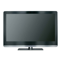
LCD COLOUR TELEVISION
LC-40LE830E/RU
LC-46LE830E/RU
LC-40LE831E/S
LC-46LE831E/S
MODELS
In the interests of user-safety (Required by safety regulations in some countries) the set should be restored to its orig-
inal condition and only parts identical to those specified should be used.








 Loading...