MX3500N ADJUSTMENTS 6 – 26
If the copy magnification ratio is not satisfactory, perform the
following procedures.
7) Remove the document table glass.
8) Remove the dark box cover.
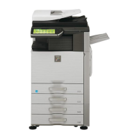
9) To prevent against shift of the CCD unit optical axis, mark the
CCD unit base as shown below.
* This procedure must be executed also when the CCD unit is
replaced.
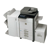
10) Loosen the CCD unit fixing screws.
* Never loosen the screws marked with ✕.
If any one of these screws is loosened, the position and the
angle of the CCD unit base may be changed to cause a
problem, which cannot be adjusted in the market. In that
case, the whole scanner unit must be replaced.
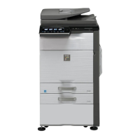
11) Slide the CCD unit in the arrow direction (CCD sub scanning
direction) to change the installing position.
When the copy image is longer than the original scale, shift the
CCD unit in the direction B. When the copy image is shorter
than the original scale, shift the CCD unit in the direction A.
One scale of mark-off line corresponds to 0.2%.
At that time, fix the CCD unit so that it is in parallel with the
scale on the front and the rear side of the CCD unit base.
* Fix the CCD unit so that it is in parallel with the line marked
in procedure 9).
12) Make a copy and check the copy magnification ratio again.
If the copy magnification ratio is not in the range of 100 ± 1%,
repeat the procedures of 9) – 11) until the condition is satisfied.
NOTE: By changing the CCD unit fixing position with the simula-
tion 48-1 adjustment value at 50, the copy magnification
ratio is adjusted within the specified range (100 ± 1.0%)
and the specified resolution is obtained based on the opti-
cal system structure.
ADJ 13 Scan image skew adjustment
(RSPF) (Refer to MX-RPX1 SM.)
ADJ 14 Scan image magnification ratio
adjustment (Document table
mode)
This adjustment is required in the following cases:
* When the copy image magnification ration in the sub scanning
direction is not properly adjusted.
* When the scanner motor is replaced.
* When a U2 trouble occurs.
* When the scanner control PWB is replaced.
* When the EEPROM on the scanner control PWB is replaced.
Before this adjustment, the focus adjustment (CCD unit installing
position adjustment) must have been completed.
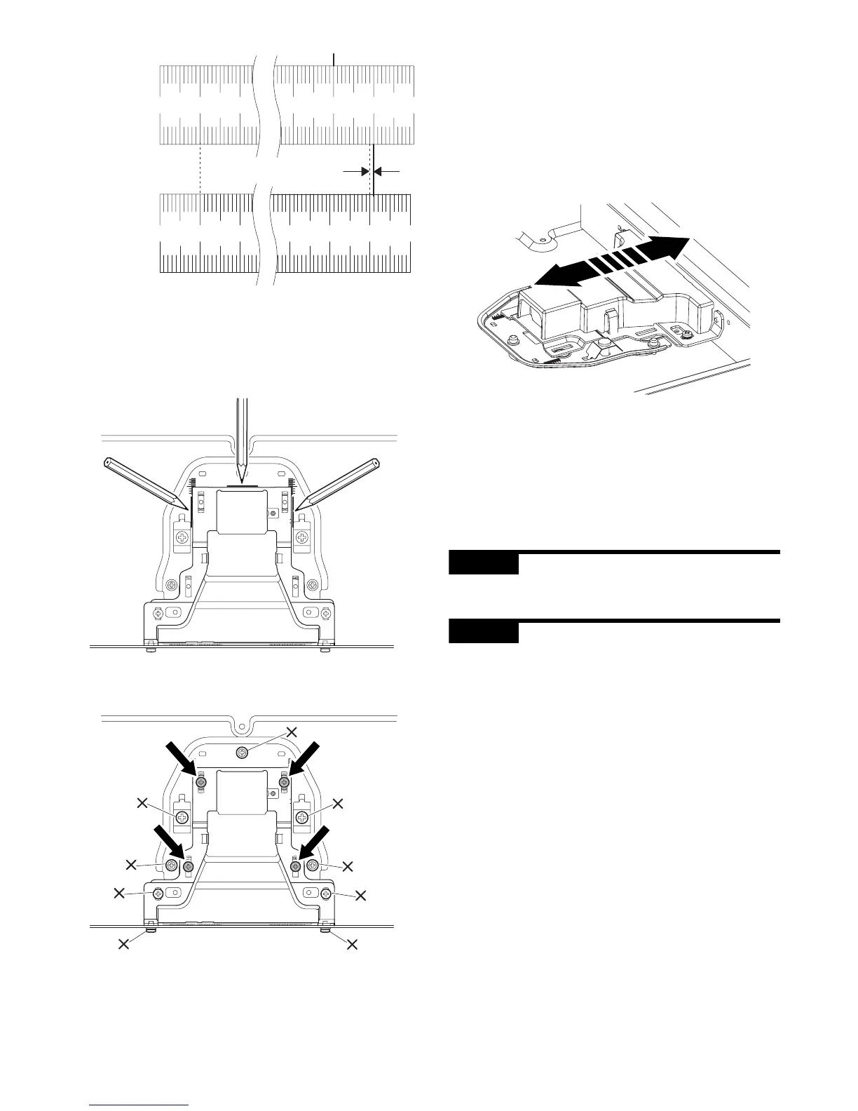
10 20 90 100 110
10 20 90 100 110
1.0mm
100mm scale
(Original)
Copy image
(1mm (1%)
shorter than
the original)
B
A