MX-C250 OPERATIONAL DESCRIPTIONS 11 – 5
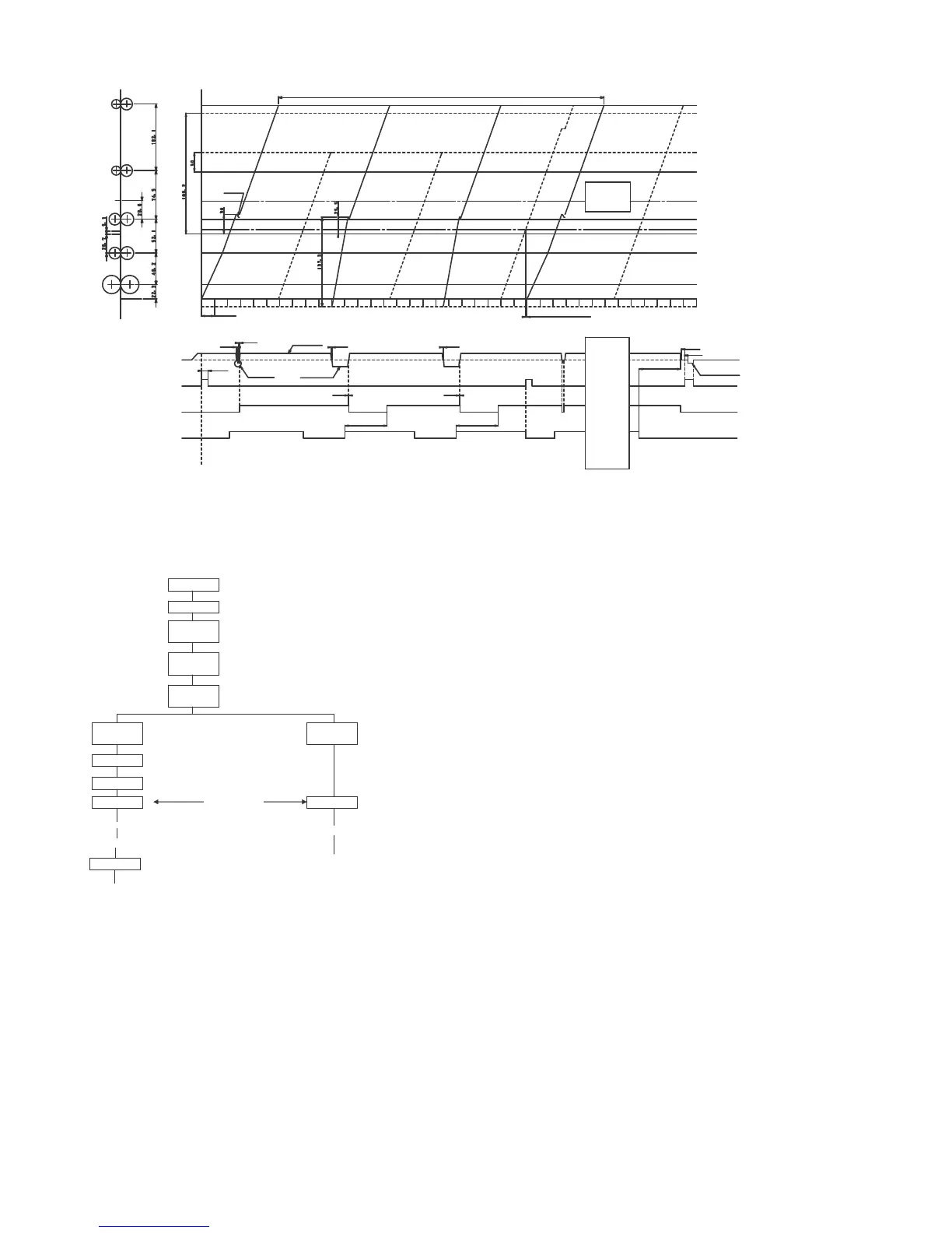
<2-sided scanning timing figure>
(2)Operation flow
(3)Original transportation
1) When the start button is pushed, the original is picked up from
RSPF tray by pick up roller, and then, transported to image
scanning position.
2) At this time, the CIS Unit is situated under the slit glass to scan
the moving original document.
3) The image on the original is scanned by the CIS Unit while the
document is moving over the slit glass.
4) For duplex original copy, after the original is scanned the original
moves towards the exit tray but does not exit.
A specific time after the lead edge of the original is detected
(depending on paper size) the paper exit rollers reverse rotation
(Switch back) and the original re-enters the paper path at the
upper transport area. Side two of the original is now ready to be
scanned.
The re-entered original (side two) is now passed over the slit glass
and scanned.
5) The original which scan completed is switched back again, then
through the original scanning position, but in this time the image
on original is not scanned, transported and exited.
6) All originals in the set sitting in the document feed tray are
scanned and exited in the same fashion as the first original.
(4)Paper transportation (main body side)
1) The paper is picked up and transported to the PS roller set from
paper cassette by pick-up roller and PS roller. After proper reg-
istration of paper timing, the image on the Primary Transfer Belt
is then transferred to the front side of the paper.
2) After transfer, the paper is separated from the belt and trans-
ported to the fusing section. In the fusing section, toner is
melted into the paper and the paper travels towards the exit
section. In this moment, the paper is not exited completely.
3) When the paper is in the exit section, if a duplex print or copy is
being produced, the paper does not exit into the paper exit tray.
The exit rollers reverse paper direction into the duplex section
where transport roller sets 4 and 5 move the paper to the Regis-
tration rollers. Side one of the original document previously
scanned is now transferred on the paper as it passes the regis-
tration rollers (after correct timing) and moves upward past the
Primary Transfer belt The paper is separated from the Transfer
Belt and moves to the fuser unit. The paper passes through the
fuser unit where the transferred toner to the paper(side 1 of the
original document) becomes melted into the paper by heat and
pressure.
After the image is transferred to the paper, the two sided copy /
print exits into the exit tray with side one facing face down allowing
the rest of the copies / prints to exit in the same order the originals
were placed in the document feed tray of the RSPF.
Reverse pulseReverse pulse
(15mm minutes)(15mm minutes)
50ms50ms
50ms50ms
255mm255mm
50ms50ms
20ms20ms
186.2mm186.2mm
50ms50ms
20ms20ms
186.2mm186.2mm
Clockwise 56mm/sClockwise 56mm/s
CounterclockwiseCounterclockwise
112m/s112m/s
Reverse Reverse
4.5mm Minutes4.5mm Minutes
50ms50ms
70ms70ms
100ms100ms
1000ms1000ms
SPFMSPFM
SPFM tranportation motorSPFM tranportation motor
SPPD1SPPD1
SPF transportation sensorSPF transportation sensor
SRVCSRVC
Reverse clutchReverse clutch
SPUSSPUS
SPF paper feed solenoidSPF paper feed solenoid
SPUFSPUF
SPPD1SPPD1
ON/OFFON/OFF
Reading positoinReading positoin
4.5mm Minute4.5mm Minute
First surfaceFirst surface
Second surfaceSecond surface
Third surfaceThird surface
Second paperSecond paper
24989ms24989ms
Paper feed solenoid is ON by SPPD1_OFFPaper feed solenoid is ON by SPPD1_OFF
Stop at 30mm from SPPD1_ON with feeding the paper. Stop at 30mm from SPPD1_ON with feeding the paper.
Stop at 25.5mm from SPPD1_ON with reverse rotation. Stop at 25.5mm from SPPD1_ON with reverse rotation.
Pickup roller is returned by the reverse rotation Pickup roller is returned by the reverse rotation
after finishing the job JOB. after finishing the job JOB.
Magnetize time : 100ms, Second paper is right after SPPD1_OFF. Magnetize time : 100ms, Second paper is right after SPPD1_OFF.
This is ON at clockwise rotation and This is ON at clockwise rotation and
this is OFF at counter clockwise when the pick up roller is put in. this is OFF at counter clockwise when the pick up roller is put in.
This is OFF in 20ms at the reverse rotation This is OFF in 20ms at the reverse rotation
after the reverse rotation is finished. after the reverse rotation is finished.
This is ON in 185.4mm after SPPD1_ON. This is ON in 185.4mm after SPPD1_ON.
(Only the last paer is OFF in 225.0mm)(Only the last paer is OFF in 225.0mm)
Each load is stopped in 255mm transportation Each load is stopped in 255mm transportation
after the last paper passes SPPD1. after the last paper passes SPPD1.