MX-C250 OPERATIONAL DESCRIPTIONS 11 – 16
B. Operational descriptions
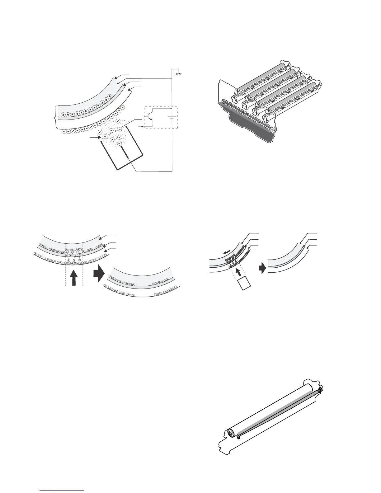
The OPC drum surface is negatively charged by the main charger,
then laser image beams are radiated to the OPC drum surface by
the laser (writing) unit to form electrostatic latent images.
1) The OPC drum surface is negatively charged by the main
charger.
The main charger grid is provided with the screen grid. The
OPC drum is charged at a voltage virtually same as the volt-
age applied to the screen grid.
2) Laser beams are radiated to the OPC drum surface by the
laser (writing) unit to form electrostatic latent images.
When laser beams are radiated onto the CGL of the OPC
drum, positive and negative charges are generated.
Positive charges generated in CGL are attracted to the nega-
tive charges on the OPC drum surface. On the other hand,
negative charges are attracted to positive charges in the alumi-
num layer of the OPC drum.
Therefore, positive charges and negative charges are bal-
anced out on the OPC drum and in the aluminum layer, reduc-
ing positive and negative charges to decrease the OPC drum
surface voltage.
Electric charges remain at a position where laser beam are not
radiated.
As a result, latent electrostatic images are formed on the OPC
drum surface.
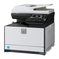
3) After transfer operation, remaining toner is removed by the
cleaning blade.
Toner removed from the OPC drum surface is transported to
the waste toner section by the waste toner transport screw.
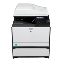
OPC drum rotation control
The OPC drum (K) is driven by the DV motor (DVM_K), and
the rotation speed is monitored by the OPC drum rotation sen-
sor (DHPD_K).
The color OPC drums (C, M, and Y) are driven by the DV
motor (DVM_CL), and the rotation speed is monitored by the
OPC drum rotation sensor (DHPD_CL).
Based on the signals monitored by the two sensors, the rota-
tion speeds of K OPC drum and the color OPC drums and the
rotation phase are controlled.
4) The whole surface of the OPC drum is discharged.
By radiating the discharge lamp light to the discharge lens,
light is radiated through the lens to the OPC drum surface.
When the discharge lamp light is radiated to the OPC drum
CGL, positive and negative charges are generated.
Positive charges generated in CGL are attracted to the nega-
tive charges on the OPC drum surface. On the other hand,
negative charges are attracted to positive charges in the alumi-
num layer of the OPC drum.
Therefore, positive and negative charges are balanced out on
the OPC drum surface and in the aluminum layer, reducing
positive and negative charged to decrease the surface voltage
of the OPC drum.