MX-C250 ADJUSTMENTS 5 – 12
4-B Print image print area adjustment
(Print engine) (Manual adjustment)
This adjustment must be performed in the following cases:
* When the LSU is replaced or removed.
* When a paper tray is replaced.
* When the paper tray section is disassembled.
* When the manual feed tray is replaced.
* When the manual feed tray is disassembled.
* When the duplex mode paper transport section is disassembled.
* When the registration roller section is disassembled.
* When the MFP PWB is replaced.
* U2 trouble has occurred.
Before execution of this adjustment, be sure to execute the print
image magnification ratio adjustment (ADJ 4A) (main scanning
direction) (print engine) (manual adjustment).
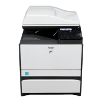
1) Enter the SIM 50-10 mode.
2) Set A4 (11 x 8.5") paper to all the paper feed trays. Select an
adjustment item of the target paper feed tray among items B -
N and enter the adjustment value. Then select item "10" to
select the paper feed tray which is to be used for executing
test printing.
3) Press [PRINT] key.
The adjustment pattern is printed.
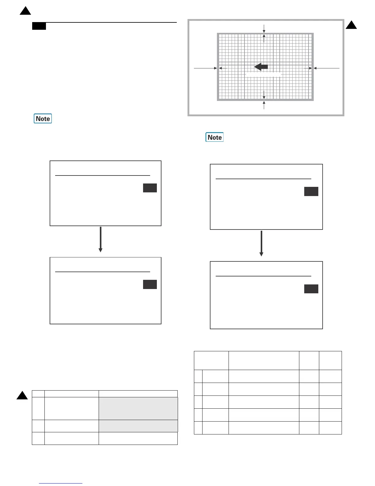
4) Check the adjustment pattern to confirm that the items below
are in the range of the standard values.
If the above condition is not satisfied, or if it is set to a desired
condition, execute the simulation 50-10.
Feed paper from all the paper feed trays to confirm.
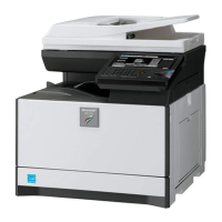
5) Enter the SIM 50-10 mode.
6) Select an adjustment item with the [UP] and [DOWN] key,
enter the adjustment value, and press [OK] key.
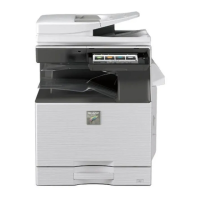
Content Standard adjustment value
X Lead edge void area
More than 4.5mm less than 5.5mm
(
total of X/Y is less than 8.0mm
X(Lead edge) is less than 5.5mm)
Y Rear edge void area
More than 2.0mm less than 3.5mm
(total of X/Y is less than 8.0mm)
Z1/
Z2
FRONT/REAR void
area
total of less than +/- 8.0mm