107
Mode 2
This mode
is
the most powerful interrupt response mode. With a single 8 bit byte from the user
an
indirect call can
be made to any memory location.
With this mode the programmer maintains a table
of
16
bit
starting addresses for every interrupt service routine.
This table may
be
located anywhere
in
memory. When an interrupt
is
accepted, a
16
bit pointer must be formed
to
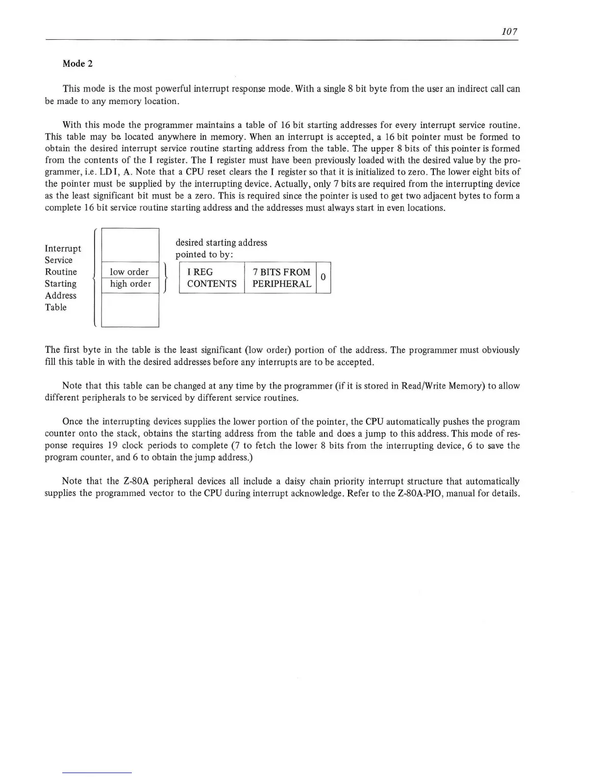
obtain the desired interrupt service routine starting address from the table. The upper 8 bits
of
this pointer
is
formed
from the contents
of
the I register. The I register must have been previously loaded with the desired value
by
the pro-
grammer, i.e . LD I, A. Note that a
CPU reset clears the I register
so
that
it
is
initialized
to
zero. The lower eight bits
of
the pointer must be supplied by the interrupting device. Actually, only 7 bits are required from the interrupting device
as
the least significant
bit
must be a zero. This
is
required since the pointer
is
used
to
get two adjacent bytes
to
form a
complete 16 bit service routine starting address and the addresses must always start in even locations.
Interrupt
Service
Routine
Starting
Address
Table
low order }
~
high order
desired starting address
pointed to by:
IREG
7 BITS FROM
CONTENTS
PERIPHERAL
0
The first byte in the table
is
the least significant (low order) portion
of
the address. The programmer must obviously
fill
this table
in
with the desired addresses before any interrupts are to be accepted.
Note that this table can be changed
at
any time by the programmer (if it
is
stored
in
Read/Write Memory)
to
allow
different peripherals
to
be serviced by different service routines.
Once the interrupting devices supplies the lower portion
of
the pointer, the CPU automatically pushes the program
counter
onto
the stack, obtains the starting address from the table and does a jump to this address. This mode
of
res-
ponse requires 19 clock periods to complete (7
to
fetch the lower 8 bits from the interrupting device, 6 to
save
the
program counter, and 6 to obtain the
jump
address.)
Note
that
the Z-80A peripheral devices all include a daisy chain priority interrupt structure
that
automatically
supplies the programmed vector to the
CPU during interrupt acknowledge. Refer to the Z-80A-PIO, manual for details.