119
An interrupt will be generated
if
interrupts from the
port
are enabled and the data on the
port
data lines satisfies
the logical equation defined by the 8-bit mask and 2-bit mask control registers. Another interrupt will
not
be generated
until a change occurs in the status
of
the logical equation. A Mode 3 interrupt will be generated only
if
the result
of
a
Mode 3 logical operation changes from false to true.
For
example, assume
that
the Mode 3 logical equation
is
an
"OR"
function. An unmasked
port
data line becomes active and an interrupt
is
requested.
If
a second unmasked
port
data line
becomes active concurrently with the first, a new interrupt will
not
be requested since a change in the result
of
the
Mode 3 logical operation has
not
occurred.
If
the result
of
a logical operation becomes true immediately prior to or during
Ml,
an interrupt will be requested
after the trailing edge
of
M
1.
6.0
INTERRUPT
SERVICING
Sometime after
an
interrupt
is
requested
by
the PIO, the CPU will send
out
an interrupt acknowledge (Ml and
IORQ). During this time the interrupt logic
of
the PIO will determine the highest priority
port
which
is
requesting an
interrupt. (This
is
simply the device with its Interrupt Enable
Input
high and its Interrupt Enable
Output
low). To
insure
that
the daisy chain enable lines stabilize, devices are inhibited from changing their interrupt request status when
Ml
is
active. The highest priority device places the contents
of
its interrupt vector register onto the Z80 data bus during
interrupt acknowledge.
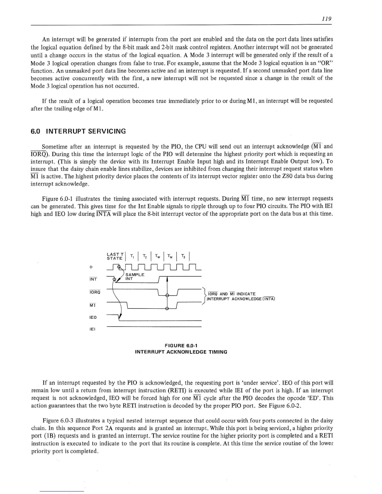
Figure
6.0-1 illustrates the timing associated with interrupt requests. During Ml time, no new interrupt requests
can be generated. This gives time for the
Int
Enable signals
to
ripple through up
to
four PIO circuits. The PIO with lEI
high and
lEO low during INTA will place the 8-bit interrupt vector
of
the appropriate port on the data bus at this time.
INT
IORQ
Ml
lEO
lEI
LAST
T I T I T
STATE
I 2
r-----
}
IORQ
AND
Ml INDICATE
INTERRUPT
ACKNOWLEDGE (I
NT
A)
FIGURE
6.0-1
INTERRUPT
ACKNOWLEDGE
TIMING
If
an interrupt requested
by
the PIO
is
acknowledged, the requesting
port
is
'under service'. lEO
of
this
port
will
remain low until a return from interrupt instruction (RETI)
is
executed while lEI
of
the
port
is
high.
If
an interrupt
request
is
not
acknowledged, lEO will be forced high for one
Ml
cycle after the PIO decodes the opcode 'ED'. This
action guarantees
that
the two byte RETI instruction
is
decoded by the proper PIO port. See Figure 6.0-2.
Figure 6.0-3 illustrates a typical nested interrupt sequence
that
could occur with four ports connected
in
the daisy
chain. In this sequence
Port 2A requests and
is
granted
an
interrupt. While this
port
is
being serviced, a higher priority
port
(!B)
requests and
is
granted an interrupt. The service routine for the higher priority
port
is
completed and a RETI
instruction
is
executed
to
indicate to the port that its routine
is
complete.
At
this time the service routine
of
the lower
priority
port
is
completed.