121
7.0 APPLICATIONS
7.1
EXTENDING THE INTERRUPT DAISY CHAIN
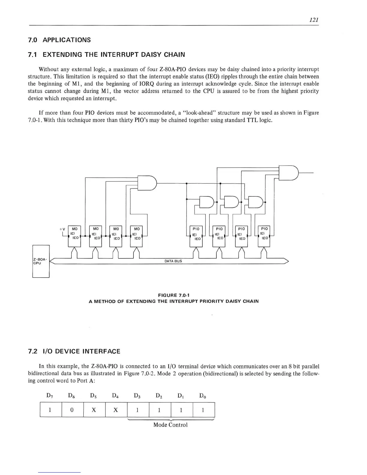
Without any external logic, a maximum
of
four Z-80A-PIO devices may be daisy chained into a priority interrupt
structure. This limitation
is
required
so
that
the interrupt enable status (lEO) ripples through the entire chain between
the beginning
of
Ml,
and the beginning
of
IORQ during an interrupt acknowledge cycle. Since the interrupt enable
status cannot change during M 1, the vector address returned to the
CPU
is
assured
to
be
from the highest priority
device which requested an interrupt.
If
more than four PIO devices must be accommodated, a "look-ahead" structure may be used
as
shown in Figure
7.0-1. With this technique more than thirty PIO's may
be
chained together using standard TTL logic.
DATA BU.S
FIGURE
7.0-1
A
METHOD
OF
EXTENDING
THE
INTERRUPT
PRIORITY
DAISY
CHAIN
7.2 1/0 DEVICE INTERFACE
In this example, the Z-80A-PIO
is
connected
to
an
1/0
terminal device which communicates over an 8 bit parallel
bidirectional data bus
as
illustrated
in
Figure 7 .0-2. Mode 2 operation (bidirectional)
is
selected by sending the follow-
ing control word
to
Port A:
Ds
0 X X
Mode Control