123
7.3 CONTROL INTERFACE
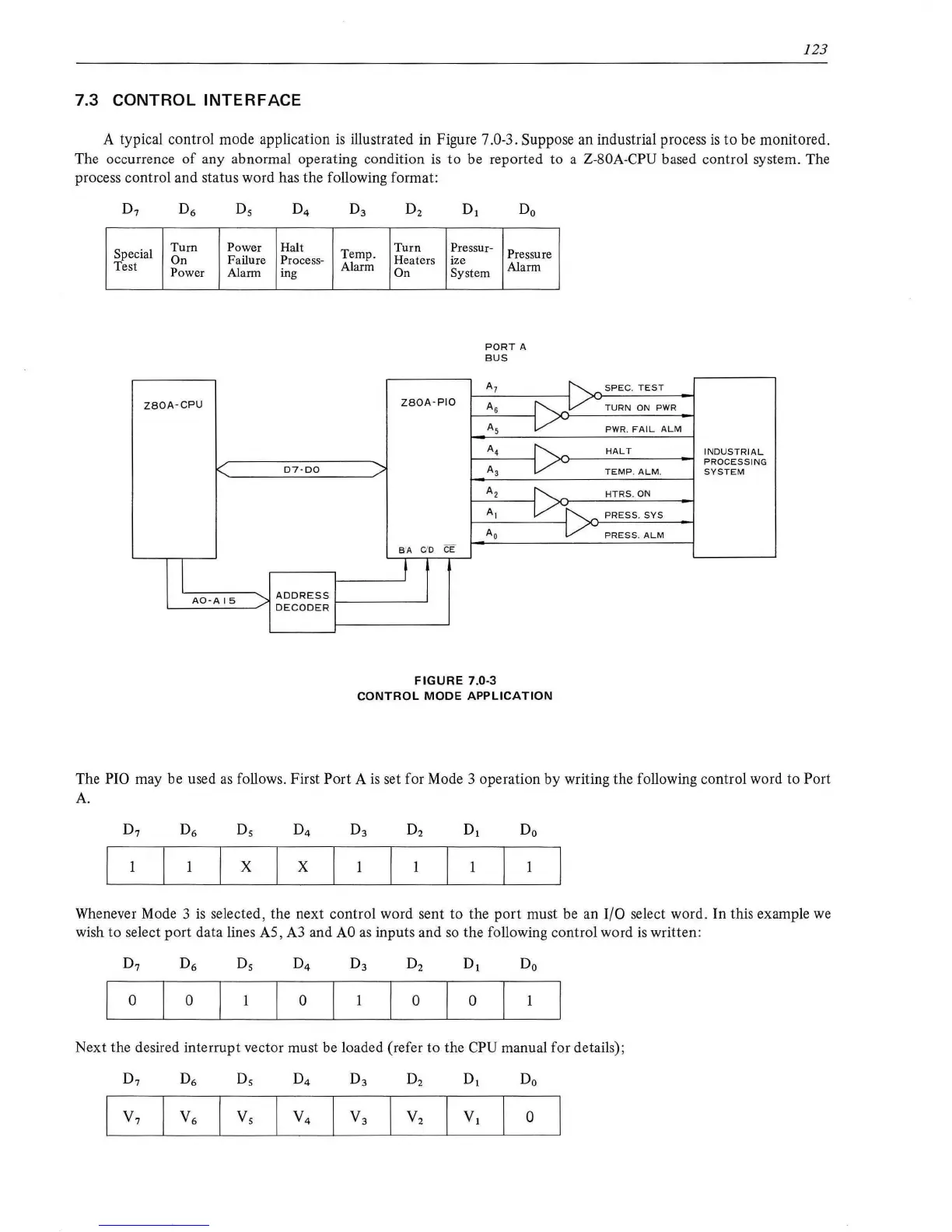
A typical control mode application
is
illustrated in Figure 7.0-3. Suppose an industrial process
is
to
be
monitored.
The occurrence
of
any abnormal operating condition
is
to
be reported to a Z-80A-CPU based control system. The
process control and status word has the following format:
Ds
Special
Turn
Power Halt
On Failure Process-
Test
Power
Alarm ing
ZSOA-CPU
D7-DO
I
AO-A
IS
"'-.,
ADDRESS
DECODER
Temp.
Alarm
>
Turn
Heaters
On
Pressur-
Pressure
ize
System
Alarm
PORT
A
BUS
A7
ZSOA-PIO
As
~---v
A5
v
A4
A3
v
A2
A,
v~
Ao
v
B"A
C'
D CE
I
t
FIGURE
7.0-3
CONTROL
MODE
APPLICATION
~SPE
C.
TEST
TURN
ON PWR
PWR.
FAIL
AL M
HALT
INDUSTRIAL
PRO
CESS
IN
G
TEMP
.
ALM.
SYSTEM
HTR
S.ON
PRESS.SYS
PRESS
.
ALM
The PIO may be used
as
follows. First Port A
is
set for Mode 3 operation by writing the following control word to Port
A.
X X
Whenever Mode 3
is
selected, the next control word sent to the
port
must be an 1/0 select word. In this example
we
wish to select
port
data lines
AS
, A3 and
AO
as
inputs and
so
the following control word
is
written:
Do
0 0
0 0 0
Next the desired interrupt vector must be loaded (refer to the CPU manual for details);
0