BUSRQ
BU
SAK
AO
-
AI5
DO
-
D?
MREQ.
RD.
~R.IO
RQ
.
RFSH
-
~
BUSRQ
Any
M
Cycle
Bu
s
Available
States
La
st
T
State
Tx
T x
~
~
~ ~
I
'/
Sample__..
Sample
I
---
r-----
----
-----
----
-----
Floating
BUS
REQUEST/ACKNOWLEDGE
CYCLE
FIGURE
3.0·4
T x
~
J
r------
-----
1-----
INTERRUPT REQUEST/ ACKNOWLEDGE CYCLE
81
T l
~
i-{
1-\
h
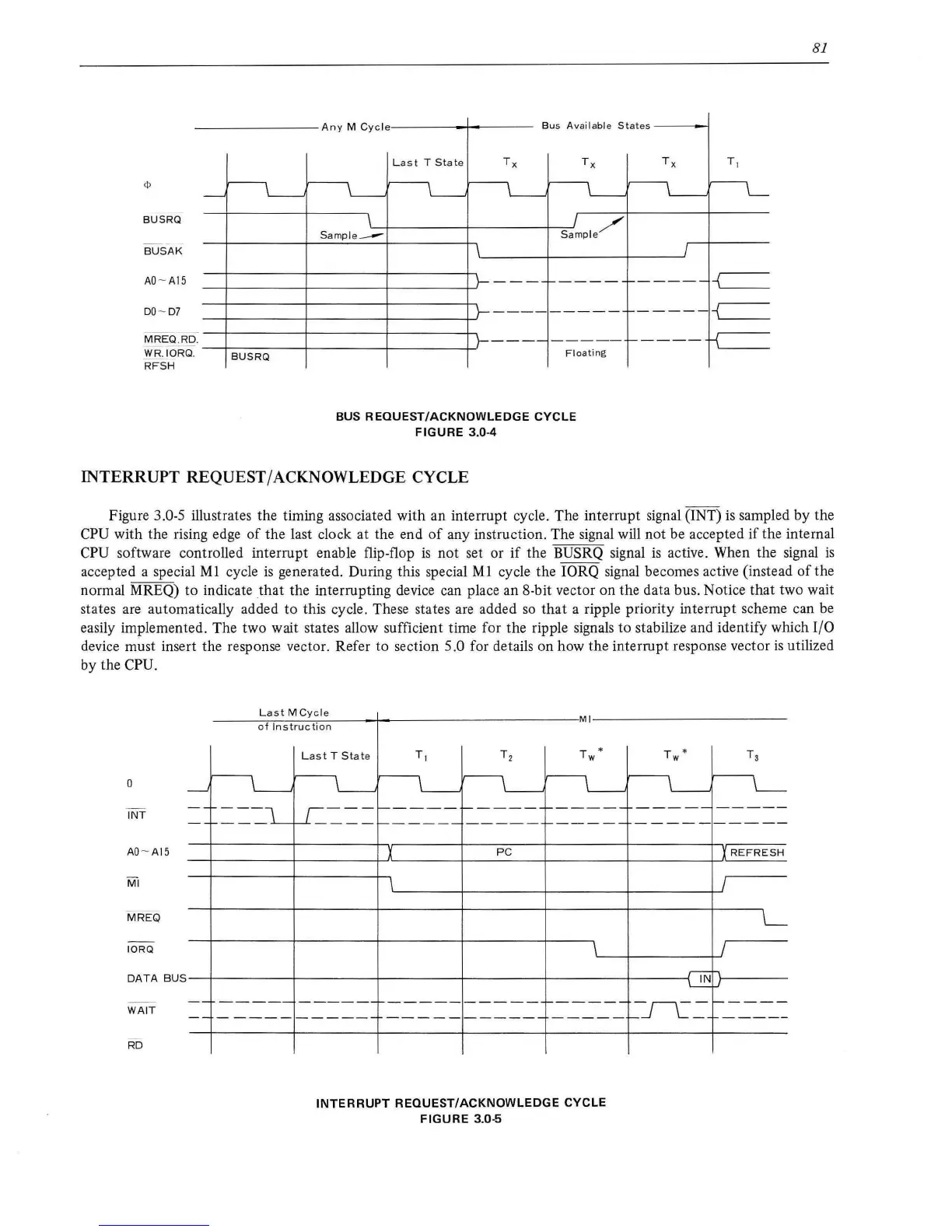
Figure 3.0-5 illustrates the timing associated with an interrupt cycle. The interrupt signal (INT)
is
sampled by the
CPU
with the rising edge
of
the last clock at the end
of
any instruction. The signal will not be accepted
if
the internal
CPU software controlled interrupt enable flip-flop
is
not set or
if
the BUSRQ signal
is
active. When the signal
is
accepted a special Ml cycle
is
generated. During this special
MI
cycle the IORQ signal becomes active (instead
of
the
normal MREQ)
to
indicate
that
the interrupting device can place an 8-bit vector on the data bus. Notice that two wait
states are automatically added
to
this cycle. These states
are
added
so
that a ripple priority interrupt
sc
heme can be
easily implemented. The two wait states allow sufficient time for the ripple signals to stabilize and identify which
1/0
device must insert the response vector. Refer to section 5.0 for details on how the interrupt response vector
is
utilized
by the
CPU.
--
INT
AO
-
AI5
MREQ
IORQ
----~L~a~s
~
t~M~C~y~c~le
____
~----------
--------------I
MI----------------
------
-
of
Instruction
La
st
T
Stat
e
T *
w
---,
I
,--------r-----
r------
___
.l...._f-1.----------
-----
r------
X
PC
T *
w
----------
X
REFRESH
IL---~---+----+----~'
\L___-+----+-''
DATA
BUS--1---------1---------~--------~--------~--------~------4f1Nh~-----
L..:.:..:.
.1
WAIT
RD
===-======--=--
-=--~---~-~=-
-~----=
--
-----
-----
------------
INTERRUPT
REQUEST/ACKNOWLEDGE
CYCLE
FIGURE
3.0-5