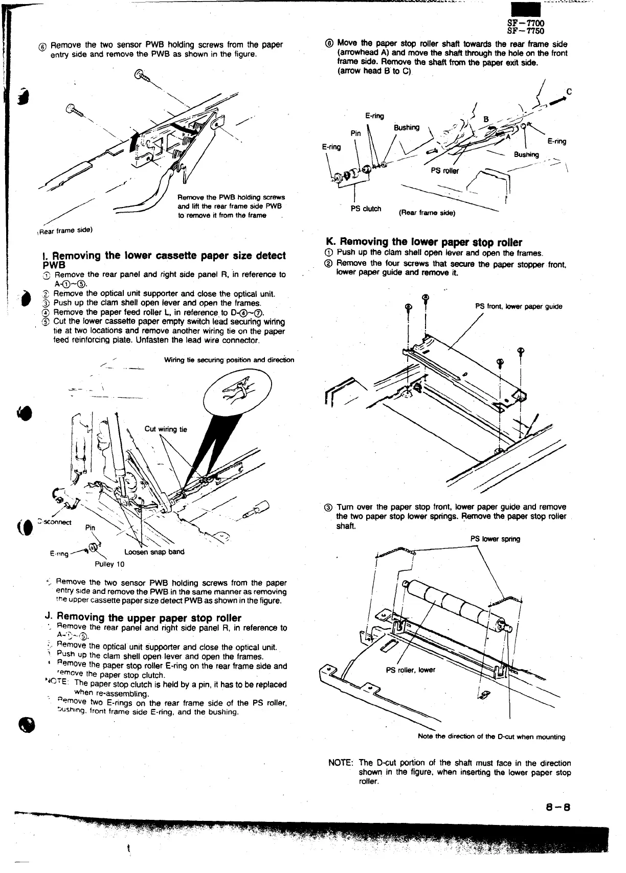
@ Remove the two sensor PWB holdingscrews from the paper
ent~
side and remove the PWB as shownin the figure.
%
‘:\.A<’
\
/
<
J“” / /.”
‘\
,/,;// #,
F
/3
~:%~.
‘v “
*
1.
9
/~
/
RemovethePWBholdiWWrews
andIifftherearframesidePWB
toremovek fromtheframe
~R”earframeside)
>Jgmoving the lower cassettepaper sizedetect
.7
Remove the rear panel and rightside panel R, ‘inreferenceto
A~-@.
Removethe opticalunitsupporterand close the opticalunit.
Push UDthe clam shelloDen lever and open the frames.
Removethe paper feed ;oller L, in referencefo D@-@.
Cut the lowercassette paper empty switchlead smring wiring
tie at two locationsand remove anotherwiringtie on the paper
feed reinforcingplate. Unfastenthe lead wire connector.
,
Wringtie~nng posti anddirdn
/
..—
SF-nOo
SF-n50
~ Move the paper stop roller shaft towardsthe rear frame side
(amwhaad A) and movethe shaftthroughthe holeon the front
frame side. Remove tie shaft fromthe paper exit side.
(arrowhead B’to C).
PS dufch
K. Removingthe lowerpaperstop roller
@
Push up the clam shellopen lever and openthe frames.
@ Remove the f~r screws that ~re the paper stopperfront,
her paper guide and remove it.
..
T,
?
PSfront,tier papergutie
;.
/
-— ,.
\
——
@ Turn aver the paper stopfront, lowerpaper guideand remove
the two paper stop lowersprings.Removethe paperstoproller
shaft.
PSfowars~ng
<; Remove the WO sensor PWB holding ~rews from the paper
entrysideand removethe pWB inthe me manneras re~Ving
the uppercassefiepaperSize dete~ p~ as showninthefigure.
J. Removing the
upperpaperstop roller
“.
Remove the rear panei and rightside panel R, in referenCeto
A.”Q-~
RemovE
the optical unit s“up~tier and close the opticalUnit..
.-,.
~ push up the clam shellown. lever and open the frameS.
I Removethe Paner Stw rollerE-rina on the rear frame side and
remove
the paper stop clutch. -
‘*OrE: ne paperstopclutchis held by a pin,it hasto be replaced
when re-assembling.
“’ aemove two E-ringson the rear frame side of the ps roller,
“~shlng.frontframe side E-ring, and the bushing.
@
NOTE:
Mte thedirtin oftheD%urmen mounting
The D~ut portionof the shaft must face in the direction
shown in the figure, when insating the lowerpaper stop
roller.
0-0
—