SF-7700
sF-m60
e
[4] COPY QUALITY ADJUSTMENTS
COpyqualitymust be adjustedfor any of the fotbting:
.At the time of maintenance.
●Afterthe drumcurrentadjustments,afterthecoronasare repfacad,
afterthe mrona wiresare rePlacad,or after a highvottageunitis
replaced.
●Afterreplacingthe CLC PWB unit or its mponents.
.After adjustingthe VR on the CLC PWB.
●Afterreplacingthe autOexposuresensor (AE).
●After replacing,adjusting,troubles-, or dis~
y of the
opticalsystem (copy lamp reflector,etc.).
●After disassembling, troubleshooting,or adjusting the optical
system.
● After replacingthe OPC drum.
●Afterrapladng the Main PWB unit.
●When the tiOUMestatus “U2” is dispfayad.
●Afterre@acerrtentof the main PWB.
●Afterreplacementof an IC (RAM IC3) withinttre main PWB.
●Afterwing the exposureContra.plate W.
1. Precautions in copy qualm adjustments
Observe the follting before performing the copy quality
adjustments.
@ Clean componentsinthaopticai system(tiglass, Ierrs,mimr,
copy lamp, and refl.~or).
@ Clean the auto exoosuresensorsurfacew& a cfotftdamDarrad
withalcohol.(UK& M0049C~-
NOTE: WiDinoWitmadrvctothwilltiusearf e
~ charge
to ~he-sensora~ will attractmore dust.
@ Clean the mrona wires (MCU, TCU).
@ Clean the developerunit.
@ Clean the area near the OPC drum.
@ Clean the OPC drumcleaningblade.
2. Copy quality adjustment pro~ure
See
the flowchartfor copy qualityadjustmm ~.
A. Descriptionof the “flowchatifor copy qualm
adjustmentprocedure
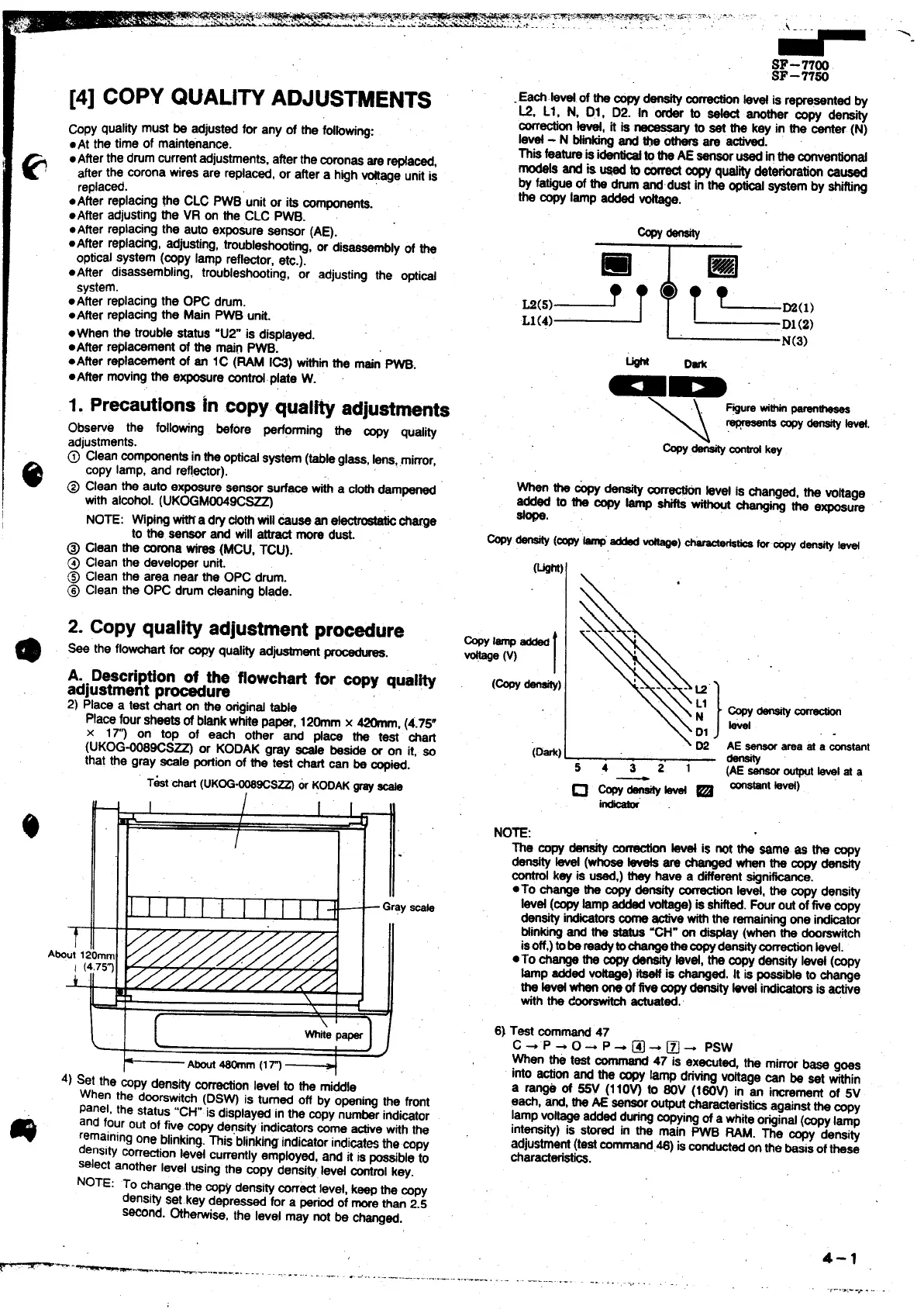
2)Place a test chati on the ~gind table
Placefoursheetsof blankwhitepaper, 120mm x 420mm, (4.75”
x 17’? on too of each other and pfa~ ~ test ~afi
T
Abut I
:OG+069Cs~ or KODAK gray tie baa or on it, so
:the gray -Ie -ion of the test chartcan be copied.
1 I I 1~ -
4) Set the &py dens~ correctionlevel to the middle
When the dwrswitch (DS~ is turned off by openingthe front
Panel,the status“CH”isdisp[ay~ in the copynumberindicator
m
and fourout of five COpydensityindi~tors come -e withthe
remainingone blinking.This”blinkingindicatorindicst~ the copy
densitycorr~ion ievel
CUrrStiIy emp~y~, and it ISpossibletO
select anotherlevel usi~ the
CODV densitylevel ~rol kav.
..
NOTE: To changethe w-py densityCorrti’levet, keepthe COW
densityset.key dapre~ for a periodof morethan2.5
*Ond. OtherwiW, the level may not be changed.
~-.
—------------ .-.
-- .,- .. ....
... .. - .-- —..... ....
- Grayscab
J
.Eacf.bvat of the copydensitym
~ kvd is representedby
L2, Ll, N, Dl, D2. In order to _ another m~ density
correctionw, it is
~ to sat the key in the center (N)
Ie@ - N btinkirrgand ~ othersare activad.
Thisfeaturais i- totfta AE
sansorusadintheconvantiortd
modek and is @ to a copy@ity deteriorationMused
by fatigueof the tim @dust in the opw @em by shifting
the copy lamp added *.
❑
.(5)- T
L1(4)
m
T L.(,,
D1(2)
N(3)
w Dark
aD
\ D2
(D*)
54321
~-~
.
sensorareaat a ~tanr
%
(AEsensoroutputtavelat a
instant kvaf)
The copy density~
fevetis not m Wmg ss h ~y
densityM (whoseteveta
arechanged~ thecopydensity
control
key is used,)they have a differentsignificance.
●To changethe ~ density~ lev~, ths qy ~si~
Ievd (copy
lampaddedvoftaga)is shifted.Fouroutoftie copy
d~sity indicatorscofrta- withthe r~nirtg one itibmr
Mnking and the status“CH”on dispfay(whenthe doorswfich
isoff,)tDbSmSdytOChSngathSCOpy_corractiorr ~vei,
●TO ti~ the q - kvd, thS-y dansty IWd (COW
~p addedx) W is changed.It is possibletochange
the Wd whenoneoffivecopy_ bet indicatorsis active
withthe d~ actuated.’
6) Test command47
c + ‘P + 0- P + @ * ~ - psw
When h test command
47 is executed, the mirrorbass
goas
into actionand the ~ lamp drivingvohagecan be sat within
a ra* of ~ (110~ to 60V (160~ in an incrementof 5V
each, and,theAE sensoroutputcharacteristi~ ag~rrstthecopy
lampvoltageaddedduringcopyingof a whiteoriginal(copylamp
int~~) is
SW~ in the main PWB RAM. The cow densi~
adjustment(tastcommati.46) ismnductadonthe basisofthese
characteristics.
4-1
-------. .- —----.-.
.. .. .. .,
.,
.1-..,:-->. ,. .