SF–7700
SF–77W
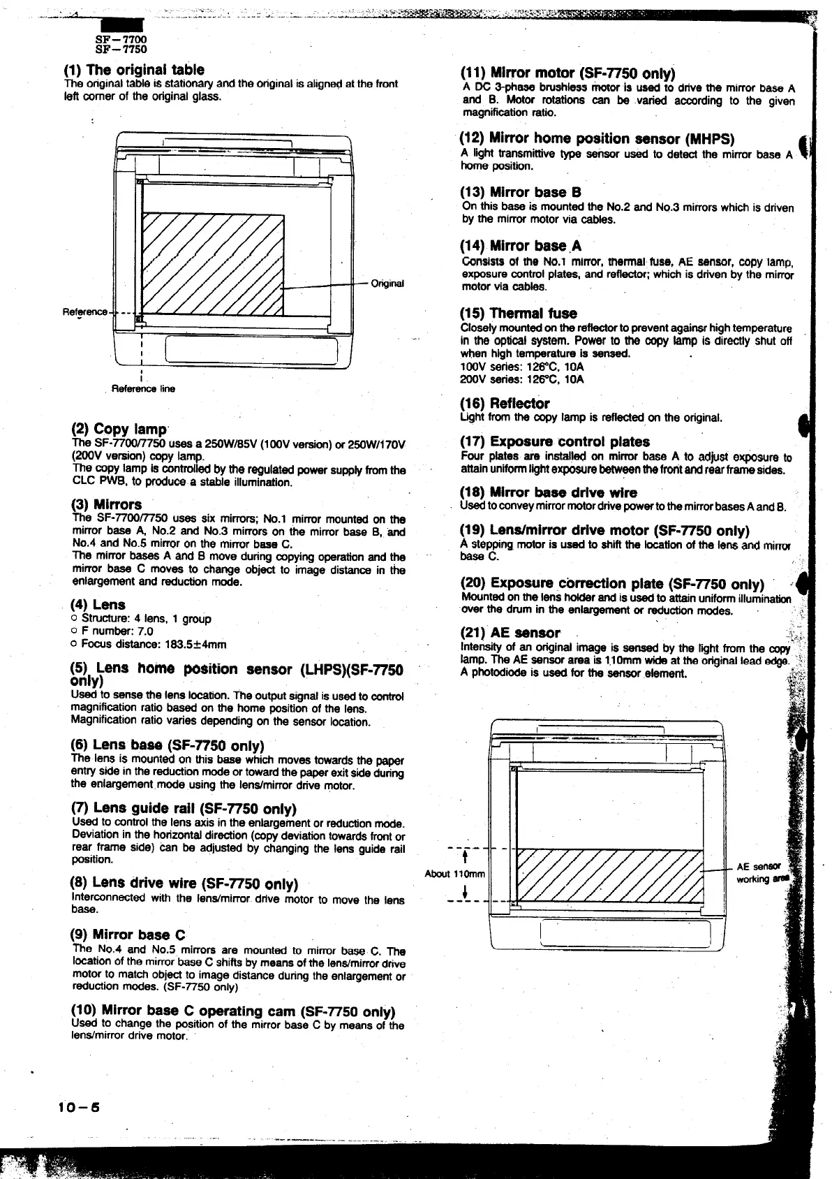
(1) fie originaltable
The originaltable is stationawand the originalis alignedat the front
left mrner of the originalgla&. - -
Refy-e
[
–
O@i@
-.
i.
Ref~
line
(2)
Co9v Iamn
~k SF-~-m7& uses a 2WW185V (1OOVversion)or 2WWI170V
(200V version)-y lamp.
The ~py lamp is wntrolled by the regulatedpowersupp~ fromthe
CLC PWB, to prgdu~.a stable illumination.
(3) Mirrors
The SF-7700~50 uses six mirrors;No.1 mirrormountedon the
mirror base A, No.2 and No.3 mi~re on the mimr base B, -
No.4 and No.5 mirroron the mirrorbase C.
The mirrorbases A and B move duringwing operationand the
mirror base C moves to cha~e obi~ to imaoe distarr~ in tie
enlargementand redution m~e.
(4) Lens
o Struaure: 4 lens, 1 group
o F number:7.o
0 FWS distance: 183.5&4rnm
g~ly;ens home position
sensor (LHPS)(SF-~50
Uti to sensethe lens i~tion. me outputsgnd is usedto _
magnificationratio based on the home positionof the lens.
Magnificationratiovaries dependingon the sensorb~tion.
(6) Lens basa(SF-~50 only)
The lens is mount~ on this bees whi~ movestowardsthe paper
enty side in the redu~ion mode ortowardthe paperexitsideduring
the enlargement.mode usingthe Ien#mirror drive motor.
(7) Lens guiderail (SF-7750only)
Used to mntroi the lens axis in the enlargementor redustionmode.
Deviationin the ~riz~t~ dir~on (@py d~ia~n t~ard$ tit or
rear frame side) mn be adjusted by changingthe lens guide rail
~sition.
(11) Minor motor(SF-7750only)
A W ~aee bruehless~or is u$5d to drtVethe mirrorba$e A
and B. Mtor rotations m be varied amrding to the given
magnifimtionratio.
(12) Mirrorhomepositionsensor(MHPS)
A lighttrsnemhtive~ sensor U- to det~ the mirror base A
home position.
(13) Mirrorbase B
ofl
this b$ee is mountedthe No.2 md No.3 mirrorswhichis driven
by the mirrormotorvia -s.
(14) Mirrorbase,A
tinsists of the No.1 mirror,thermal fuse, AE sensor, mpy lamp,
exposuremrrtrolplates,and re~or; whichis ddven by the mirror
motorvia *s.
(15)~ermal fuse
Closelymountedontheretiorto preventagairterhgh temperature
in the optioalSystem. POWr to the oopy ~p is dirtiy shut off
men hightemperatureis sensed.
100V sefies: 12&C, 10A
200V series: l~C, 10A
(16) Refl~or
Lightfrom the sopy lamp is retied on the original.
(17)
Exposurecontrolplates
Fwr pktes are installedon mirrorbase A to adfist e~sure to
attainuniformlightexposurebetweertthewtand rearframesides.
(18) Mirrorbase drivewire
UsedtosonveymirrormotordrivepowsrtothemirrorbasesA andB.
(19) Len#mirrordrivemotor(SF-7750only)
A
step@ng,motoris usedto ahiftthe ktion of the kns and mirror
base
c.
(20) Exposure,titiion plate(SF-7750only) I
Mountedonme Ms hotderandis usedto attainuniformillumimtiorf
over the dmm in the enlargarnent or redu*n modes. .’
(21)”AEsensor ‘”
:$,..
./
Intensityof an originalimage is sensed by the Ight from the ~:
lamp.~ AE sensorarea is l,lomm wide at the originallead edga ‘
A photodiodeis used for the sensorelement.
.&~
---- -
t
tit llOmm
(8) Lensdrivewire (SF-7750only)
lnter~nn~ed with the IenWmirror.drive motor to move the lens
i
---- -
base.
(9) Mirrorbase C
The No.4 and No.5 mirrors are mounted to mimr b-C. The
Iosstionofthe mirrorbaseC shiftsby meansofthe len#mirrordtive
motorto matchobjti to image distanceduringthe enlargementor
redudion modes. (SF-~50 only)
(10) Mirrorbase C operatingcam (SF-7750 only)
Used to change the ~sition of the mirrorbase C by meansof me
Ien#mirror drive motor,
I
+)
—...—.—..—.
u——,
I
.
10–6